3step 2, Step 3, Step 4 – Craftsman 351.21833 User Manual
Page 3
3
STEP 2
• Use the blade tilt handwheel to tilt the blade completely to
45
°.
• Remove the packing material from behind the motor.
• Return blade to the 0
° position.
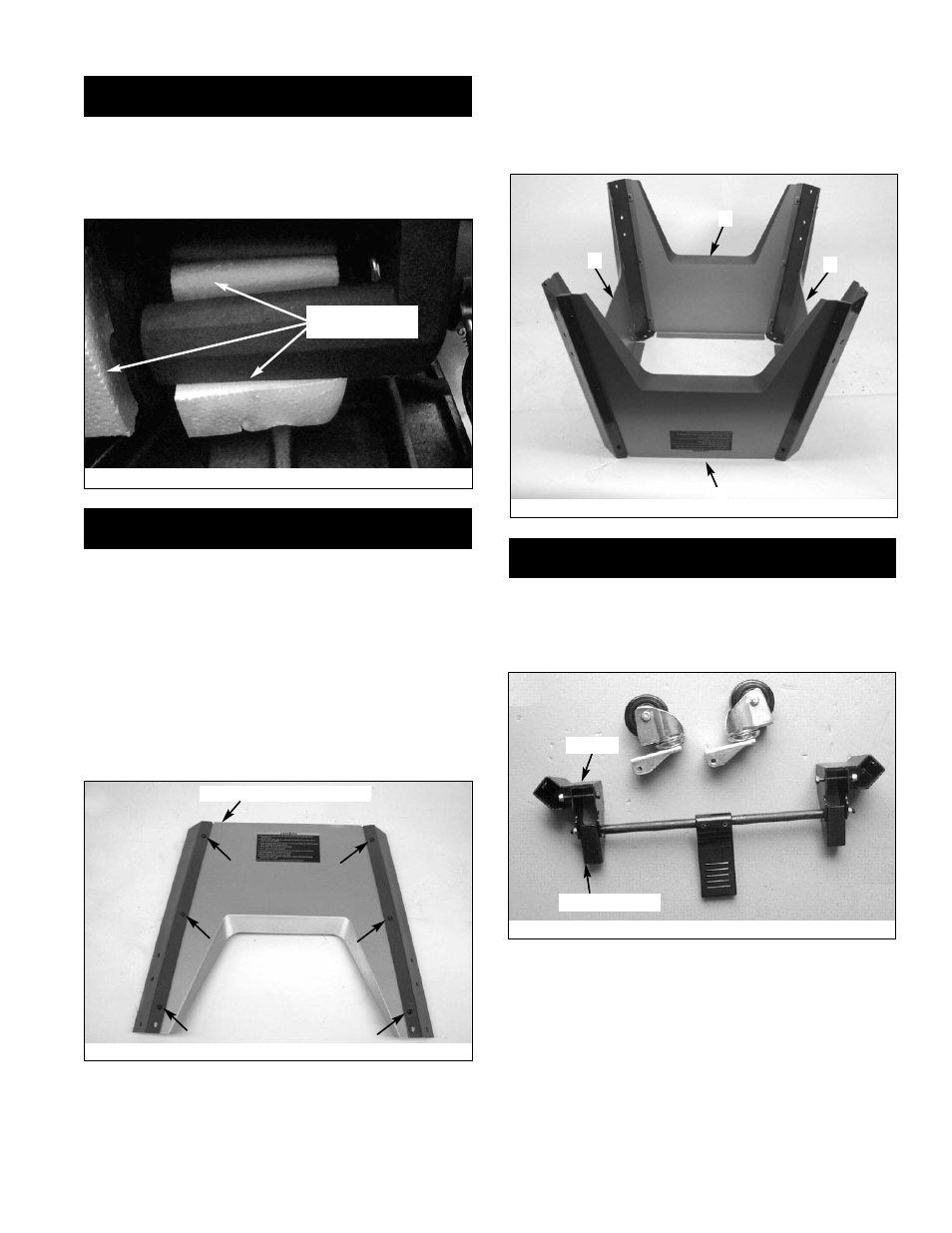
STEP 3
ASSEMBLE MOBILE BASE PANELS
Tools Required: 4mm Hex Wrench
Hardware Required: Twenty-four M6 x 12 socket pan head
bolts (Hardware bag #4).
• Attach the front panel between the two corner supports
using six M6 x 12 socket pan head bolts.
Note: Place the panel edges INSIDE the corner support
surfaces.
Note: Front panel and rear panel are both stamped ‘A’.
Front panel has warning label.
• Repeat above step for the rear panel.
• Set both panel assemblies upside down on bench and
attach the left side panel (stamped ‘B’) to the assemblies
made above.
• Attach the right side panel (stamped ‘C’) to the assembly.
Below is completed base assembly.
STEP 4
ASSEMBLE CASTER SETS
Tools Required: Two
1
⁄
2
″ Open End Wrenches
• Refer to Figure 6; remove casters (4) and supports (2)
from carton.
Figure 4
Figure 5
Letter Stamp On Top Edge
Figure 3
Remove this
packing material
A
A
Kick Plate Cam
Bracket
B
C
Figure 6