Pa300, Pa360 – FBT QUBE PA User Manual
Page 7
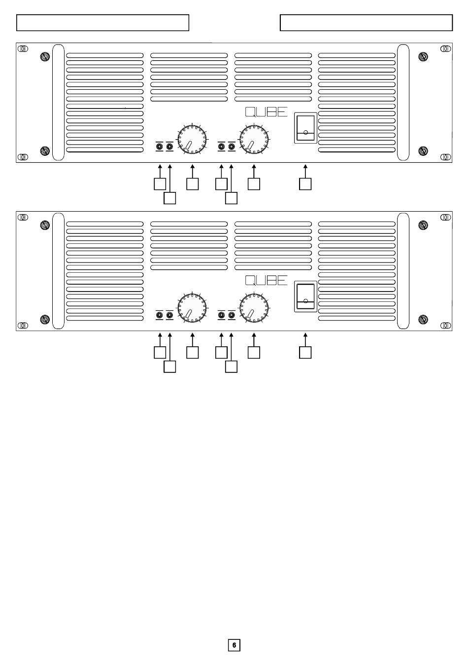
FRONT PANEL FEATURES
PA 300 / PA 360
10
0
10
PA300
CH2
POWER
G
G
R
R
PWR
PWR
SIG
SIG
PROT
PROT
CLIP
CLIP
0
10
0
10
PA360
POWERAMPLIFIER
CH1
CH2
POWER
G
G
R
R
PWR
PWR
SIG
SIG
PROT
PROT
CLIP
CLIP
1
2
3
1
2
3
4
1
2
3
1
2
3
4
1. Channels status (PROT / PWR) led
2. Channels signal (SIG. / CLIP) led
3.Channel output attenuator
4. Power on / off switch
The channel 1 & 2 status led glows green to indicate the amplifier is on and channel is operating normally. It glows red to
indicate that one or more of the amplifier channel protective circuits has been activated. The amplifier contains separate over-
temperature, DC on output and shorted-load protective circuitry for each channel. Whenever a fault is detected the offending
channel is temporarily “shut down” and the status light turned red to call attention to the problem. The channel will remain “off”
until normal operating conditions are restored.
It is normal for the status led to glow red when the amplifier is first turned on. It will then turn to a steady green as a sign that
channel is on and operating satisfactorily.
The signal led indicates the status of the amplifier’s channel signal level. When it is off (not glowing) it shows that no signal is
being received. It glows green to indicate a normal signal level and red as an indication that channel is being driven into
clipping. Occasional operation of the red “clip” indication (flickering of the red light)is an indication of optimum system
utilization. Extended illumination of the red “clip” indication is a sign the system is being overdriven and shoud be avoided.
The channel output attenuator controls the gain of channel in all operating modes. When it is turned fully clockwise, the
amplifier will have its maximum rated voltage gain and will deliver it rated output when driven by its rated input signal. As a
general rule, setting the attenuator in the full clockwise position provides maximum amplifier headroom; setting the
attenuators at a lower level maximizes the system signal/noise ratio.
This switch is used to turn power to the amplifier “on” and “off”
Note: The status led is also controlled by the SP12 and SP22 controllers and when one of these modules is included, the
status led will glow red when one of these modules’ protective circuits has been activated.
Important: When the amplifier is being operated in the bridge output mode, both the channel 1 and channel 2 attenuators must
be set in the same position to avoid a mismatch in the signal level being sent to each channel.