Rear panel features, Pa 140, Standard input module – FBT QUBE PA User Manual
Page 6
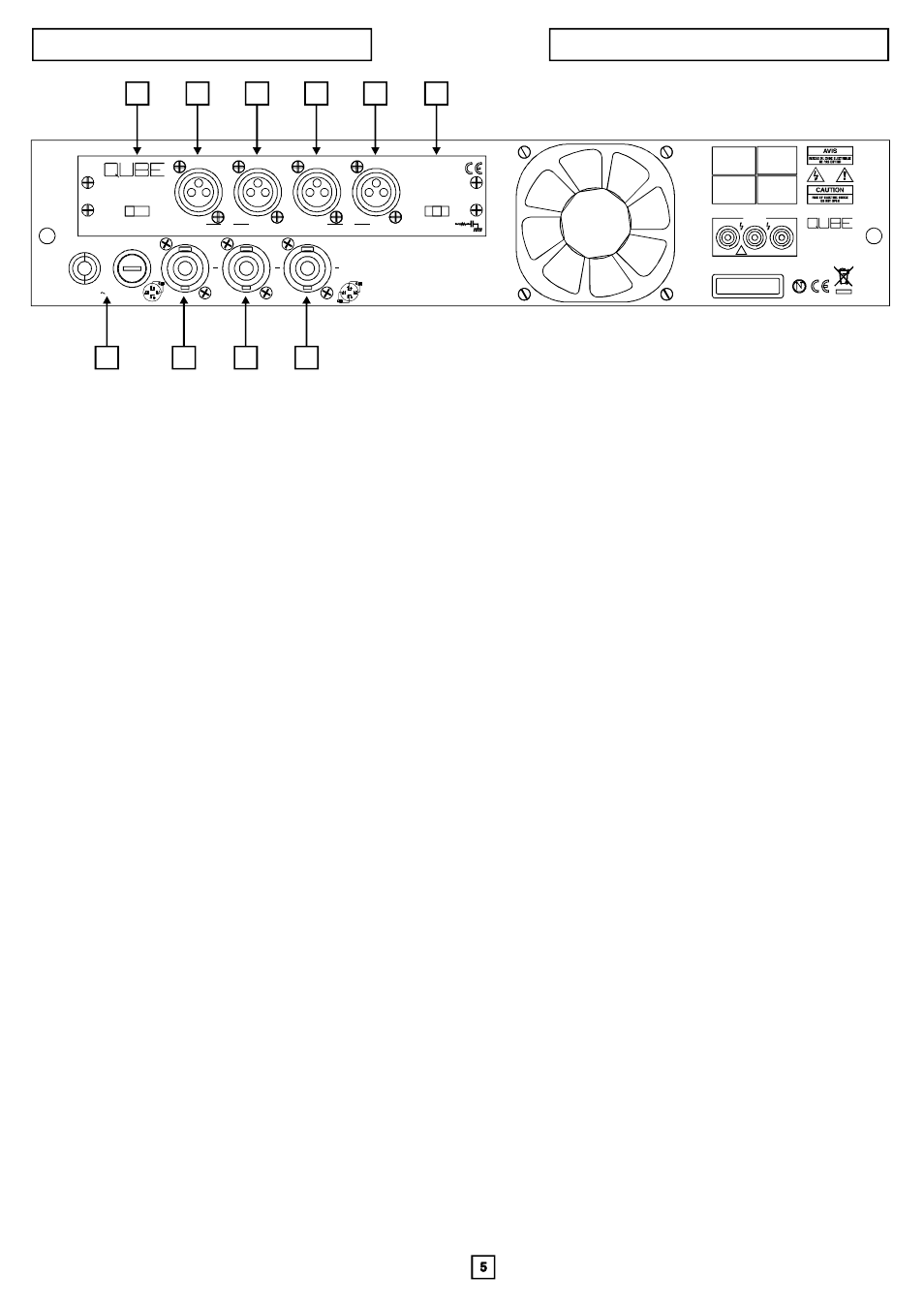
REAR PANEL FEATURES
1
2
3
4
5
6
7
8
9
10
1. AC power cord & fuse
2. Channel 2 output connector
3.Bridge output connector
4. Channel 1 ( and 2 ) output connector
The fuse holder on the PA 140 accepts a T10A, 250V.
4-pin Neutrik Speakon connector provides single-connector, quick-disconnect facilities for channel 2 on pins 1+ & 1-. Pin 1+ is considered
the “hot” terminal while pin 1- is “common”.
4-pin Neutrik Speakon connector provides single-connector, quick-disconnect facilities for the amplifier’s bridge output on pins 1+ & 1-. Both
pins 1+ and 1- are considered “hot” and should not be grounded.
4-pin Neutrik Speakon connector provides single-connector, quick-disconnect facilities for both channel 1 and channel 2 outputs. The
channel 1 output is on pins 1+ and 1- and the channel 2 output on pins 2+ and 2-. Pins 1+ and 2+ are considered “hot” while pins 1- and 2- are
“common”.
Before connecting the amplifier check the AC voltage requirement and make certain the unit is connected to the proper voltage. Failure of
the unit will result if a 120 volt amplifier is connected to a 220V power line.
PA 140
230 V
50 Hz
T 1 0 A
250 V
OUTPUTS
2
STEREO 4 OHMMIN.
BRIDGED MONO 8 OHM MIN.
POWER CONSUMPTION:920 W
!
CLASS2WIRING
C H 2
C H 1
BRIDGE
OUTPUT
MANUFACTUREDINEEC
WARNING
CAUTION
CAUTION
CAUTION
TOREDUCETHERISKOF
ELECTRICSHOCKDONOT
EXPOSETHISEQUIPMENT
TORAINORMOISTURE
TOAVOIDELECTRICSHOCK
DONOTINSERTFINGERS
OROBJECTSINTOANY
OPENINGSINTHECABINET
TOREDUCETHERISKOF
ELECTRICSHOCKDONOT
REMOVETHECOVER.NO
USERSERVICEABLEPARTS
INSIDE.REFERSERVICINGTO
QUALIFIEDSERVICEPERSONNEL
FORCONTINUEDPROTECTION
AGAINSTRISKOFFIRE
REPLACEONLYWITHSAME
TYPEFUSE
PA140
POWERAMPLIFIER
2
PM22
STEREO
GROUND LIFT
PARALLEL
ON
ON
IN
IN
OUT
OUT
OFF
link
link
BRIDGE
(CH1 IN)
PIN1=GND
P I N 2 =
P I N 3 =
+
-
Standard input module
5. Stereo-Parallel-Bridge outputmodeselector
stereo
parallel
bridge
6. Channel 2 audio input connector
7.Channel 2 “looping output” connector
8. Channel 1 “looping output” connector
The outputmodeselector allows the amplifier to be operated in 3 different outputmodes.
In the
mode the two channels operate independently, just as they do in a stereo amplifier: signals fed into the two amplifier inputs are
amplified separately and delivered in phase to outputs 1 and 2. The output levels are controlled separately by the front panel mounted
attenuators.
In the
mode input 2 is disabled and the two amplifier channels operate in parallel from a single input signal fed into the channel 1
input. This eliminates the need to install a jumper cable to operate the amplifier channels in parallel. The outputs are separate and in phase
and both input attenuators are active to permit different level settings for each channel.
In the
mode a single signal is fed into the channel 1 input which drives both output channels in tandem. The output is delivered to the
bridge output connector. This mode allows the two amplifier outputs to be strapped together (”bridged”) to produce a single output with
double the power capabilites of a single channel. Input 2 is disabled. Both input attenuators are active and must be set to the same level.
Note that in bridge mode both sides of the output should be considered hot and should not be grounded.
Female 3-pin XLR type input connector for channel 2. The input is electronically balanced.Werecommend the use of pin 2 as “hot” and pin 3
as “neutral”. Pin 1 is chassis ground.When the amplifier is connected to a balanced source the shield may either be lifted or connected at the
source end. The choice should be made on the basis ofminimum hum.
With an unbalanced source connect the signal to pin 2 and source ground to pin 3; connecting the signal to pin 3 is not recommended as this
will cause a 180 phase inversion at the amplifier outputs.
Male 3-pin XLR type “looping output” connector for channel 2 used to “loop through” to additional amplifiers.
Note: improper operation results when only pin 2 or only pin 3 and pin 1 (ground)
are used for an unbalanced input.
Male 3-pin XLR type “looping output” connector for channel 1 used to “loop through” to additional amplifiers.
Female 3-pin XLR type input connector for channel 1. Refer to “6” above for details.
The Ground Lift switch is used to separate the signal ground circuit from the amplifier ground circuit and thus, eliminate hum induced by
ground loops.
In the left “ON” position the signal ground is electrically disconnected from the amplifier ground circuit (the chassis).
In the center “OFF” position the input signal ground is electrically connected to the amplifier ground circuit (the chassis).
In the right “ON” position an AC connection is provided between the signal ground and the amplifier ground circuit (the chassis).
9. Channel 1 audio input connector
10. Ground lift switch