Evolution engines auto-choke ignition system, Installation of the auto-choke ignition unit, The spark ignition included with your evolution – Evolution Engines EVOE116GX2 User Manual
Page 9: Technical data, Other features
8
evolution engines Auto-choke Ignition System
The spark ignition included with your Evolution
®
gas engine is a modern generation electronic ignition. There are many useful
functions built into the microprocessor of this unit.
In addition to the basic ignition functions, the unit has a FAIL-SAFE feature: After 90 seconds of inactivity it automatically switches to
an inactive state. In order to restart normal operation, it is necessary to turn the battery switch off and then back on. This function will
preserve battery life should the switch be left in the on position during inactivity.
Installation of the Auto-choke Ignition unit
While installing the ignition unit in your model, be careful to have all parts that are connected to the unit and the engine situated
as far as practical from the radio receiver and radio antenna. The throttle servo should be mounted a distance of 8–12 inches from
the engine. The spark plug cable must not touch any part of the model structure as vibration may damage the cable. If this is not
practical, it will be necessary to provide an insulation material for the cable. The ignition unit itself should be wrapped in foam rubber
to prevent engine vibration from damaging the electronics. All components must be protected from contact with engine fuel.
Technical data
Weight:
155 g
Power supply:
3x Li-lo/Li-Po 11.1V
9x Ni-Cd/Ni-MH 9–13V
Pre-ignition point:
5º
L ocation of the magnet:
240º / 120º
M inimum battery capacity:
1 Ah
other features
Auto-Choke Ignition System
Choice of pre-ignition curve
Customizable pre-ignition curve*
S leep mode after 90 seconds of engine inactivity
Battery level signalization
I gnition goes off if engine runs counterclockwise
*will be released later
LOW
BATTERY
SLEEP
MODE
SHORT
SILENCER
LONG
SILENCER
0
10
0
m
s
20
0
m
s
30
0
m
s
40
0
m
s
50
0
m
s
60
0
m
s
70
0
m
s
80
0
m
s
90
0
m
s
1
se
c
1.
1
se
c
1.
2
se
c
1.
3
se
c
1.
4
se
c
light
dark
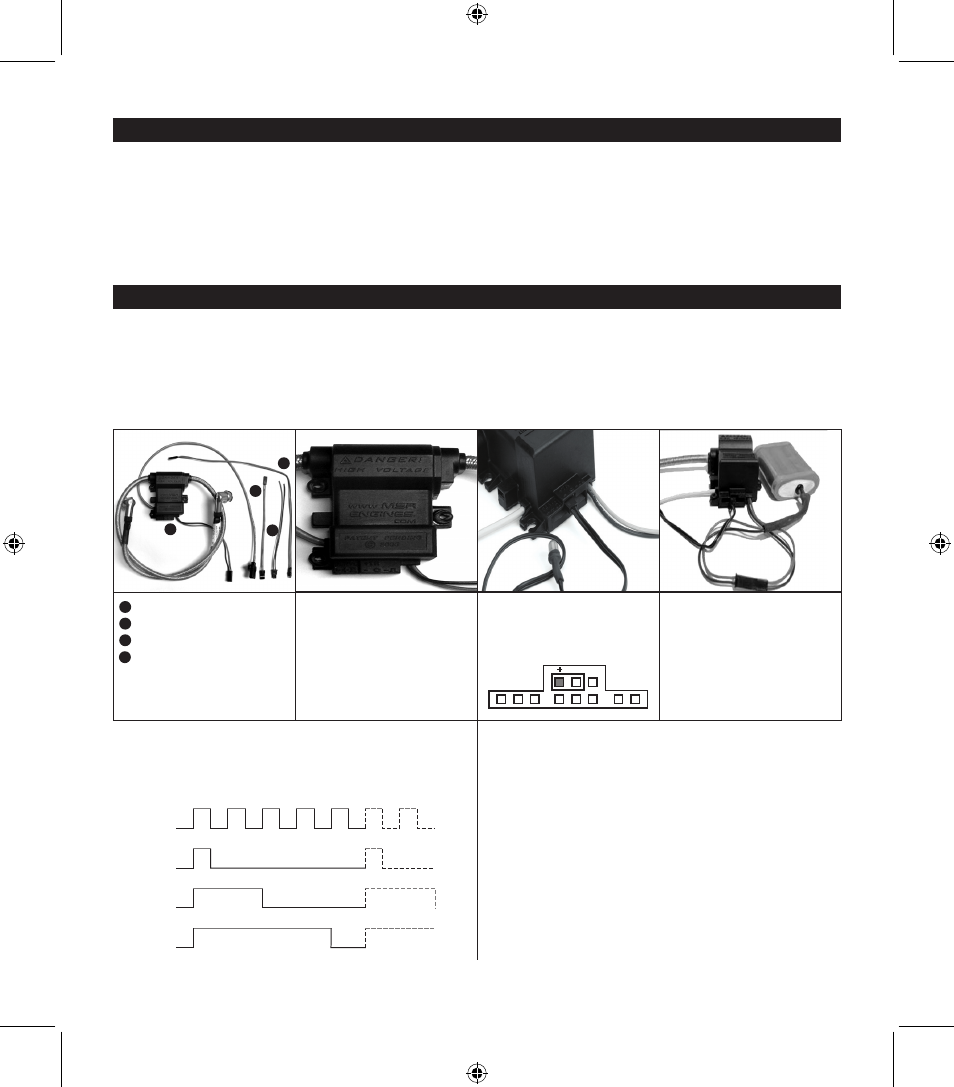
LED Blinking Patterns
1
Ignition
2
LED
3
Programming cable
Power cable
ICU–B
9–13V
C onnect LED indicator to the ignition
box (red/black wire to “+”).
U sing the included connector, plug your
battery pack into the ignition box.
F ive seconds after connecting the
battery, the LED indicator should go
out. If the LED is blinking after you
connect the battery, the battery’s
voltage is too low.
2
3
4
4
LeD
1
9477.3_EVO116GX2_Manual.indd 8
4/20/07 3:13:56 PM