ETS-Lindgren HI-3603 VLF Survey Meter User Manual
Page 28
HI-3603 VDT/VLF Survey Meter
© ETS-Lindgren, August, 2005
Revision E, Part # H-600042
28
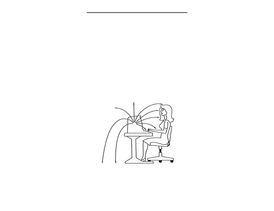
ELECTRIC AND MAGNETIC FIELD LINES
Figures 7 and 8 illustrate how the electric and magnetic field
lines are typically directed near a VDT. There are significant
differences in the perturbation effect caused by the presence of
the operator relative to electric and magnetic fields. Because of
capacitive coupling between the operator and ground, the
operator tends to bring the existing ground potential up nearer
the VDT and emerging electric field lines terminate on the
operator. Thus the electric field component of maximum strength
will be that which is normal to the surface of the exposed body;
components of electric field parallel to the body's surface are
shorted out and vanish because of the relatively highly
conductive nature of the body tissues. Consequently,
measurements of operator exposure to electric fields, made with
a displacement type of detector, must be accomplished with the
sensor oriented such that incident field lines strike the sensitive
electrode plate at a normal angle. In this way a measure of the
maximum electric field strength is obtained.
Figure 7: Electric field lines incident on the VDT operator
are perpendicular to the body surface.