ETS-Lindgren HI-3603 VLF Survey Meter User Manual
Page 18
HI-3603 VDT/VLF Survey Meter
© ETS-Lindgren, August, 2005
Revision E, Part # H-600042
18
The digital display response is digitally filtered for increased ease
of operation. This smooths the response to rapidly changing
fields. In some measurement situations, however, it may be
helpful to increase the response of the digital display, ie. reduce
the response time. This is done when the instrument is turned
on. Refer to KEYPAD MATRIX in this section, and the operation
of the E/H keypad for details.
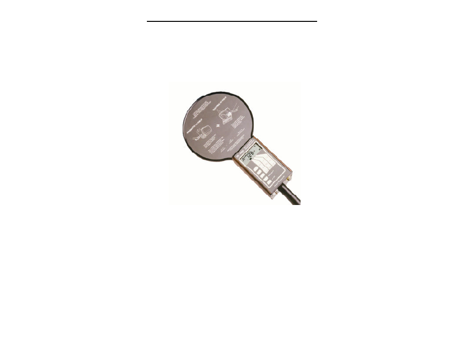
Figure 5: HI-3603 VDT/VLF Survey Meter
The default display response filter is F-2 (refer to KEYPAD
MATRIX in this section for more information). The instrument will
normally be received from the factory with this setting (F-2). The
display response setting is stored in the non-volatile memory of
the HI-3603 and if the setting is changed, the new setting will be
saved and will become the default condition. For this reason, we
recommend that you check the display response setting when
you first receive the instrument and after battery replacement.
The display response setting does not affect the accuracy of the
instrument.
The battery condition is indicated by a small "battery" symbol in
the lower left corner of the LCD. As the battery voltage
decreases, the low battery symbol begins to blink. If the battery