Installation – Environmental Water Systems FU Series User Manual
Page 4
Unpack the HEATER GUARD. Unit comes complete with the following:
5 micron pre-sediment filter with poly-phosphate spheres, housing with cap and mounting bracket, pressure
differential gauge, spanner wrench (other mounting bracket included with all HEATER GUARD-3/4)
HEATER GUARD CAN BE REVERSED FOR FLOW DIRECTION FOR ANY INSTALLATION.
HEATER GUARD-3/4:
Flow direction is from left to right. If installation calls for the reverse direction use the other mounting bracket
provided, turn Heater Guard-3/4 around (meter reads from either side) and install using the other
mounting bracket so flow direction can be from right to left.
HEATER GUARD-1.5:
Flow direction is from left to right. If installation calls for the reverse direction remove the 4 screws from
bracket and turn bracket around and reconnect so flow direction will be from right to left. Turn gauge
1/2 turn clockwise only in order to read.
WARNING: Do Not Loosen the gauge during this procedure.
NOTE:
Whether you use the standard flow direction from left to right or you reverse the installation for the flow
direction from right to left - the inlet side is always designated by a flow direction arrow on the filter cap.
Identify an appropriate mounting location adjacent to the water heater. The HEATER GUARD can be mounted in both
indoor and outdoor locations.
Turn off the water supply. Route the cold water supply into the inlet side of the HEATER GUARD.
HIGHLY RECOMMENDED: Install a bypass with shut-off valves for maintenance convenience (see pictures below).
NOTE: APPLICABLE FOR ALL METAL PIPING: Installed bypass maintains electric continuity for the proper ground of
plumbing system. If not installed, a jumper is needed (copper wire clamped) between any metal piping before and
after the unit to maintain the proper ground.
Connect the outlet side of the HEATER GUARD into the cold inlet of the water heater. Refer to water heater instructions
for more information on specific water heater connections and water heater start-up procedures.
Turn on the water supply slowly to allow housing to fill with water.
Depress the RED pressure release button on top of filter cap to release trapped air from the filter.
Check for leaks before leaving installation.
Installation
www.ewswater.com O: 702.256.8182; M-F 8:30am-4:30pm PST E: [email protected]
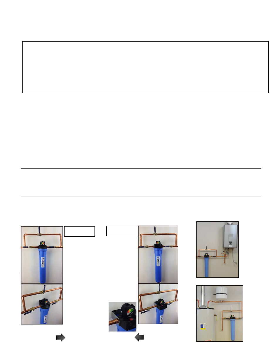
Pictured:
EWS-HEA
TER-GUARD-3/4
installed
with
bypass
at
the
inlet
to
a
typical tankless water heater
Pictured:
EWS-HEA
TER-GUARD-3/4
installed
with
bypass
at
the
inlet
to
a typical water heater
Under no circumstances does the EWS Heater Guard change or alter the proper application and/or routine
maintenance required or recommended by the manufacturer of any product.
WARNING:
Do not overtighten or cross-thread any connections into the inlet or outlet of the cap assembly.
Do not overtighten the housing into the cap assembly. Do not remove the meter or gauge.
Pictured:
EWS-HEATER-GUARD-3/4
STANDARD
INSTALLATION
Flow direction
from
left to right.
REVERSE
INSTALLATION
Flow direction
from
right to left.
Use other
mounting
bracket
Note:
meter on 3/4” unit
can be viewed from
either side
For 11/2” unit
reverse bracket and
turn guage 1/2 turn
clockwise to view
Pictured:
EWS-HEATER-GUARD-3/4
direction of flow
direction of flow
Inlet Outlet
Outlet Intlet
1.
2.
3.
4.
5.
6.
7.
WARNING:
Do not allow to freeze and avoid direct sunlight or heat. Prevent any thermal expansion or hot water back into
HEATER GUARD from water heater.