Directory
Brands
Dynojet manuals
Hardware
Analog Module
Manual

Dynojet Analog Module User Manual

Page 8

  • Text mode
  • Original mode
background image

Analog Module Installation and User Guide

C H A P T E R 1
Analog Module Installation

1-4

4

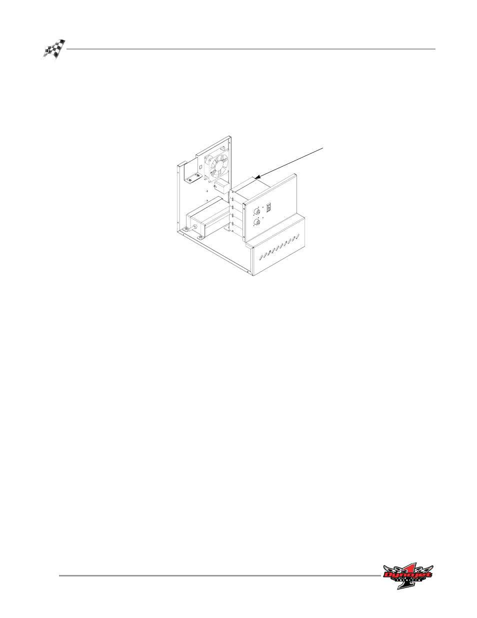
Add the Analog Module to the top of the dyno electronics. Refer to “Installing the
Analog Module” on page 1-5.

5

Leave the dyno electronics enclosure out. You will need to route any sensor
cables to the Analog Module as they are installed.

Figure 1-2: Inside the Electronics Enclosure

dyno electronics

Pages: 1 … 6 7 8 9 10 … 21
  • wrong Brand
  • wrong Model
  • non readable
See also other documents in the category Dynojet Hardware:
  • Compressed Air Pump Assy & Remote BOB Upgrade (2 pages)
  • Spring Applied Air Release (SAAR) Brake Assembly (27 pages)
  • Optical RPM Sensor (22 pages)
  • Proportional Air Brake (21 pages)
  • Flow Meter (22 pages)
  • Air Pump Troubleshooting Guide (2 pages)
  • Air Pump III Troubleshooting Guide (2 pages)
  • Air Fuel Ratio Module (36 pages)
  • Tire Temperature Sensor (10 pages)
  • Data Link Module - HD Delphi ECM (18 pages)
  • Data Link Module - OBDII (33 pages)
  • Compressed Air Air/Fuel Ratio Module (33 pages)
  • Wideband Commander Air/Fuel Ratio Monitor (4 pages)
  • O2 Sensor Test Gas Usage Procedure (1 page)
Home Brands Popular manuals Recently added
Manuals Directory

© 2012–2025, azmanual.top
All rights reserved.