Routing the analog module cable assembly, Routing the analog module cable assembly -6 – Dynojet Analog Module User Manual
Page 10
Analog Module Installation and User Guide
C H A P T E R 1
Analog Module Installation
1-6
R
OUTING
THE
A
NALOG
M
ODULE
C
ABLE
A
SSEMBLY
1
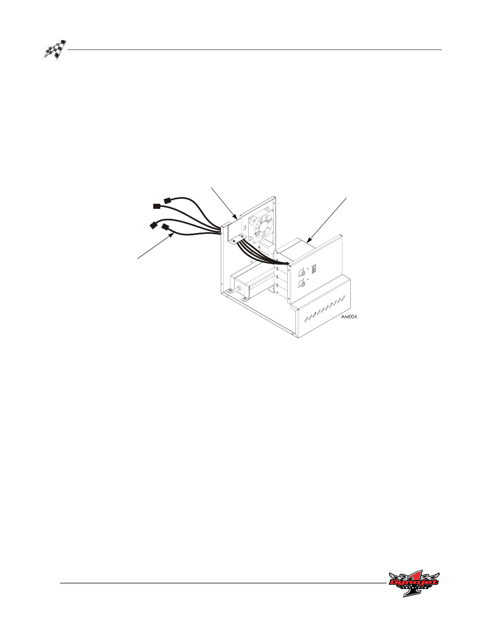
Route the Analog Module cable assembly through the cable clamp on the back of
the dyno electronics enclosure.
1a
Loosen the two screws and lift the clamp up to slide the analog cable
through.
1b
Secure the clamp with the two screws.
2
Attach the connector on the Analog Module cable assembly to the front of the
Analog Module.
Figure 1-5: Attach the Analog Module Cable Assembly to the Analog Module
analog module
cable clamp
analog module
cable assembly