To figure 6, Cable location and figure 7 fo – Dynojet Proportional Air Brake User Manual
Page 12
Proportional Air Brake Installation Guide
P R O P O R T I O N A L A I R B R A K E
Installation
8
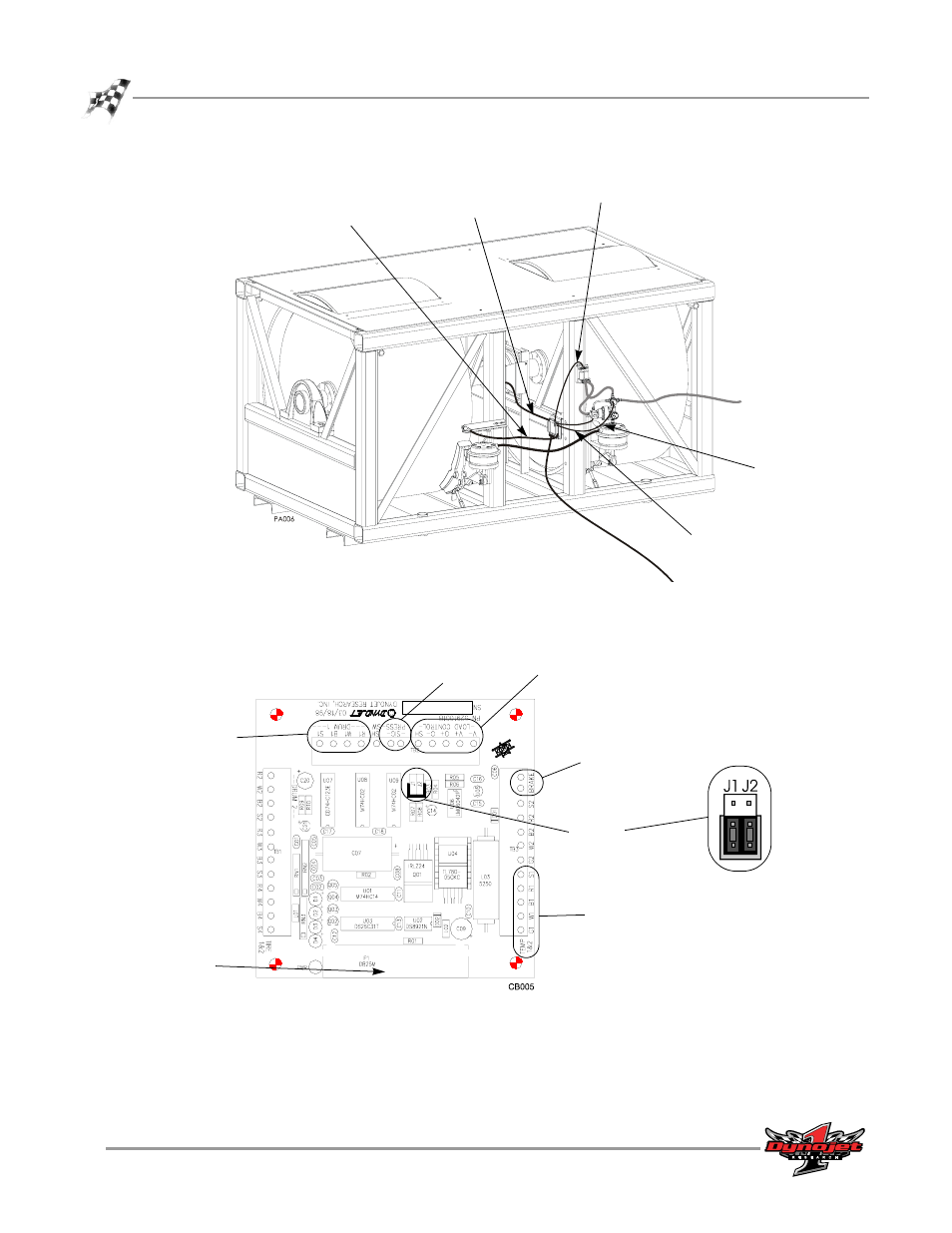
Figure 6: Routing Cables—Breakout Board
6
The Breakout board jumper settings are preset, however, verify jumpers J1 and J2
are set for the proportional air brake as shown in Figure 7.
Figure 7: Prop Air—Wiring the Breakout Board
EPR cable
data acquisition
cable
brake solenoid
wires
air pressure
switch wire
temperature
sensor cable
drum 1
press
load control
brake
temp
DynoWare
cable
jumpers
J1 and J2
prop air brake
jumper settings
This manual is related to the following products: