Installation, Connecting the optical rpm sensor, Connecting the optical rpm sensor -3 – Dynojet Optical RPM Sensor User Manual
Page 9
O P T I C A L R P M S E N S O R I N S T A L L A T I O N
Installation
Optical RPM Sensor Installation Guide
1-3
. . . . . . . . . . . . . . . . . . . . . . . . . . . . . . . . . . .
INSTALLATION
This section describes the procedures for installing the optical RPM sensor.
C
ONNECTING
THE
O
PTICAL
RPM S
ENSOR
1
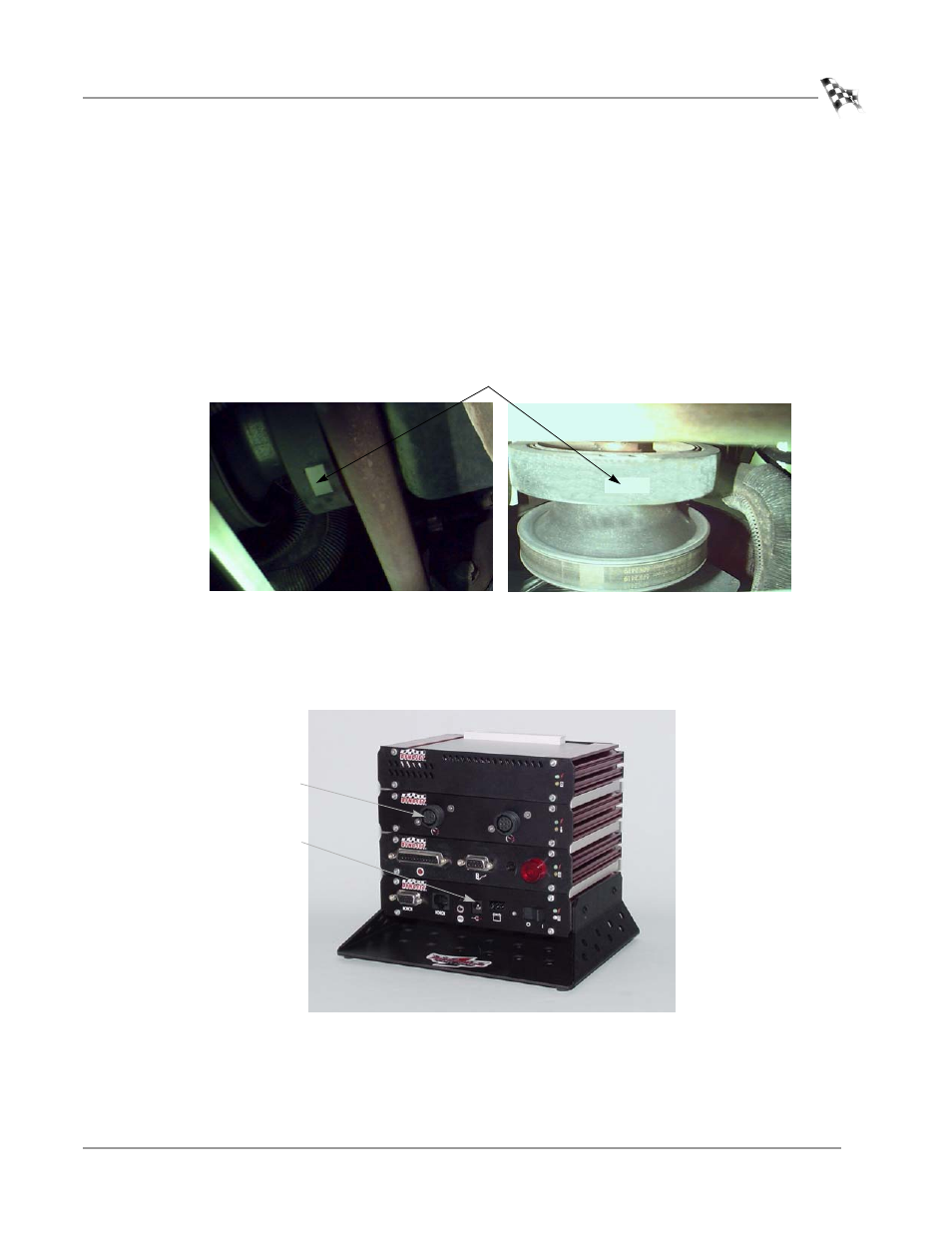
Cut a one inch strip of reflective tape from the roll provided.
2
Clean a flat section of the harmonic balancer. Attach the strip of reflective tape.
Note: High RPM engines will require a longer piece of reflective tape; use a
1.25-1.5-inch strip of tape.
Figure 1-2: Attach Reflective Tape To Harmonic Balancer
3
Attach the optical sensor lead to the hardware stack. You need to remove any
inductive leads from the RPM module if installed.
4
Attach the small power lead from the optical sensor lead to the CPU module.
Figure 1-3: Hardware Stack—Optical Sensor and Power Lead
reflective tape
optical sensor lead
on RPM module
optical sensor power
lead on CPU module