Vlink – Code 3 vLink User Manual
Page 7
7
Z3 SIREN APPLICATION (cont.)
Connections
Wiring varies according to which model variant of
vLink you are installing. In all cases, +12VDC power
and system ground connections must be routed to the
location where the vLink controller will be mounted.
Using the supplied Power Cable assembly, connect
the red wire to a +12VDC Ignition Power source
that is fused at 1A. It’s important that the vLink be
powered from an Ignition switch power source so that
a Power On Reset occurs each time the vehicle is
started. Connect the black wire to vehicle ground at a
point that offers a low resistance path to the battery’s
negative terminal.
Route the control cable from the vLink Controller to
the Z3 Siren and connect per the User Manual. For
Z3 installations, route the CAT5 cable from the vLink
Controller to the Z3. Connect the CAT5 cable to the
“AMP-2” port on the Z3.
When all connections are made, turn on the vehicle’s
ignition and continue on page 18.
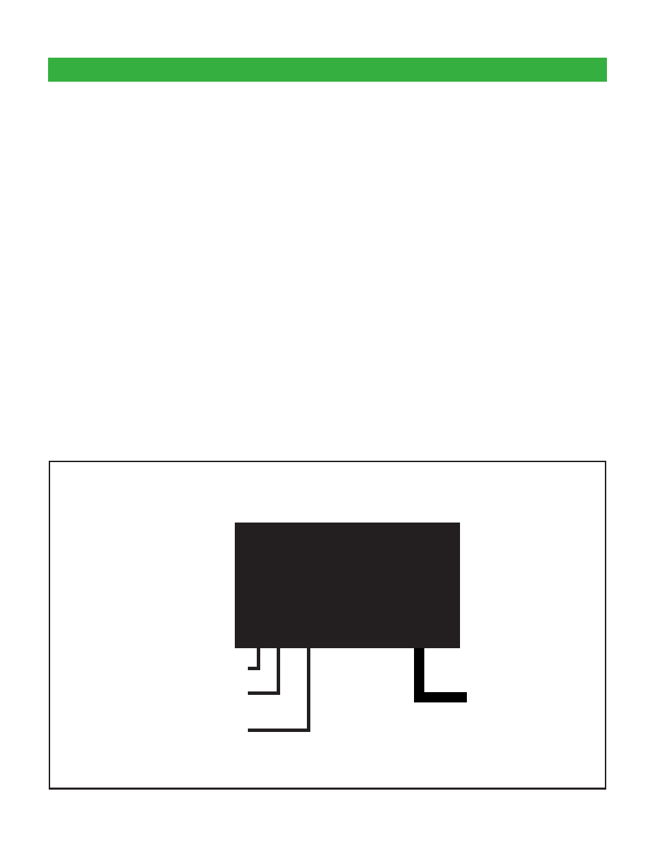
Typical Wiring for vLink-Z3
vLink
TM
Z3 Siren Connection
(CAT 5)
Coax Antenna Cable Connection
Ignition Switched +12VDC (fused
@ 1A)
Ground