Installation, Led operation – Code 3 Torus Lighthead User Manual
Page 4
Installation:
This unit can be mounted to metal surfaces using two #8 x 1/2 pan head
sheet metal screws (included). This unit can also be mounted to plastic
surfaces using two #8 x 1/2 pan head machine screws (included). The
cable routing hole (3/8" minimum diameter) can be drilled to match the
wire exit. An optional rubber gasket, included with the unit, may be used
to prevent oxidization and galvanization of the mounting surface due to
metal-on-metal contact.
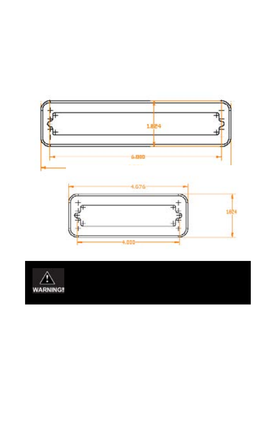
Figure 1 6-LED
Figure 2 3-LED
4
3-LED Operation
The 3-LED model can communicate with other 3-LED units via a
PARENT / CHILD relationship as described in the following sections.
Wiring
The Black wire is the Ground wire and the Red wire is the Power (+)
wire. The White wire is used for flash pattern selection and it is also used
to set the PARENT or CHILD mode. The Grey wire is used for commu-
nications between the PARENT and CHILD. Attach the Grey wire of the
PARENT to the Grey wire of any other head (s) set in CHILD mode to
coordinate Alternating or Simultaneous flash patterns between heads.
If the product is to be used inside the vehicle, it may cause severe
personal injury if not properly mounted and secured. Objects
used in vehicle may become airborne during a collision or other
sudden changes in vehicle speed or direction, such as braking,
acceleration or turns.