Installation instructions – Code 3 Tahoe Citadel User Manual
Page 2
2
Installation
Instructions
Tools Needed
10mm Socket
T25 Torx Driver
Torque Wrench
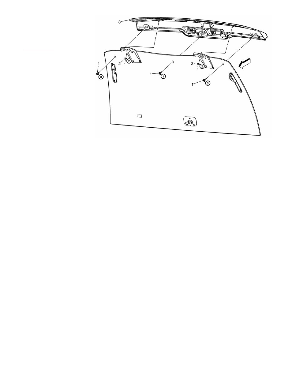
Step-1. Raise rear glass and locate the fasteners attaching the rear spoiler to the glass (Qty:5).
Step-2. Remove Torx fasteners (Qty:3) followed by 10mm nuts (Qty:2).
Step-3. Raise spoiler away from the vehicle to expose the electrical connector for the third brake light and disconnect.
Step-4. Remove spoiler from vehicle and lay part on a protected surface to prevent scratches.
Step-5. Remove 10 mm nuts from brake light assembly.
Step-6. Position Right/Left Citadel assembly over brake light fasteners.
Step-7. Reinstall 10 mm nuts from brake light assembly.
Step-8. Pull out the grommet, disconnect the other end of the wiring for the third brake light and discard the OEM third-
brake light wiring (This part of the OEM wiring will be replaced by the Citadel cable and wiring).
Step-9. Route the Citadel cable following the path of the OEM brake light wiring & then route the Citadel Cable the
rest of the way as desired. Plug the appropriate connector from the Citadel brake light wires into the connector of the
vehicle's OEM wire harness for the third brake light. Pull the slack out of the Citadel Cable and plug the Citadel's grom-
met back into the grommet hole in the vehicle. Plug the opposite end connector of the Citadel brake light wire into the
vehicle's OEM connector in the spoiler for the third brake light. (Note: the other Citadel wires in shrink tube should be
positioned under spoiler).
Step-10. Place spoiler on the vehicle. Position the center spoiler screw first, followed by the hinge nuts second. Note:
make sure none of the wires are pinched as you reinstall the spoiler!
Step-12. Install the outer screws last and torque the screws in the same sequence. Torque screws to 18 lb in
Torque nuts to 80 lb in.
Step-13. The light heads in the CELS version of the Citadel are all STEADY BURN ONLY and require the CELS
controller for power, lighting sequence, and flash patterns. See the Instruction Manual for the CELS-CC Hous-
ing for wiring connections and flash patterns.