Unpacking & pre-installation, Installation & mounting – Code 3 SuperVisor TL for Chevy Impala User Manual
Page 3
3
Unpacking & Pre-installation
Carefully remove the SuperVisor™ and place it on a flat surface, taking care not to scratch the lenses or damage the cable coming
out of the side. Examine the unit for transit damage, broken lamps, etc. Report any damage to the carrier and keep the shipping
carton.
Standard light bars are built to operate on 12 volt D.C. negative ground (earth) vehicles. If you have an electrical system other than
12 volt D.C. negative ground (earth), and have not ordered a specially wired light bar, contact the factory for instructions.
Test the unit before installation. To test, touch the black, (and if present grey, purple, and brown) wire(s) to the ground (earth) and the
other wires to +12 volts D.C., in accordance with the instructions attached to the cable (an automotive battery is preferable for this
test). A battery charger may be used, but please note that some electronic options (flashers, stingrays, etc.) may not operate
normally when powered by a battery charger. If problems occur at this point, contact the factory.
Installation & Mounting
Mounting Hardware - All mounting hardware is packed in a small box inside the main carton. There are four brackets used to mount the
visor bar to the vehicle. These are discussed in detail later.
Utilizing non-factory supplied screws and/or mounting brackets and/or the improper number
of screws may result in loss of warranty coverage on the equipment.
WARNING!
!
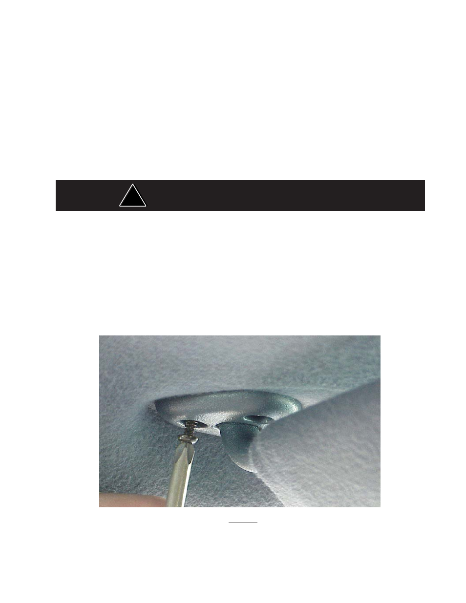
FIGURE 1
Removing Sun Visors
Begin the installation by removing the Chevrolet Impala's driver and passenger sun visors. Identify each visor with tape or other
marking to indicate the driver from the passenger side unit. They are not identical. There are three screws that hold the pivotal arm of
the sun visor to the headliner. Remove the two outer screws using a small torx screwdriver. Then unclip the sun visor and rotate it over
to expose the last screw as shown in Figure 1.