Wiring - ranger, Flash pattern selection - ranger, Warning – Code 3 Ranger User Manual
Page 6: Routing
6
wiring - Ranger
TM
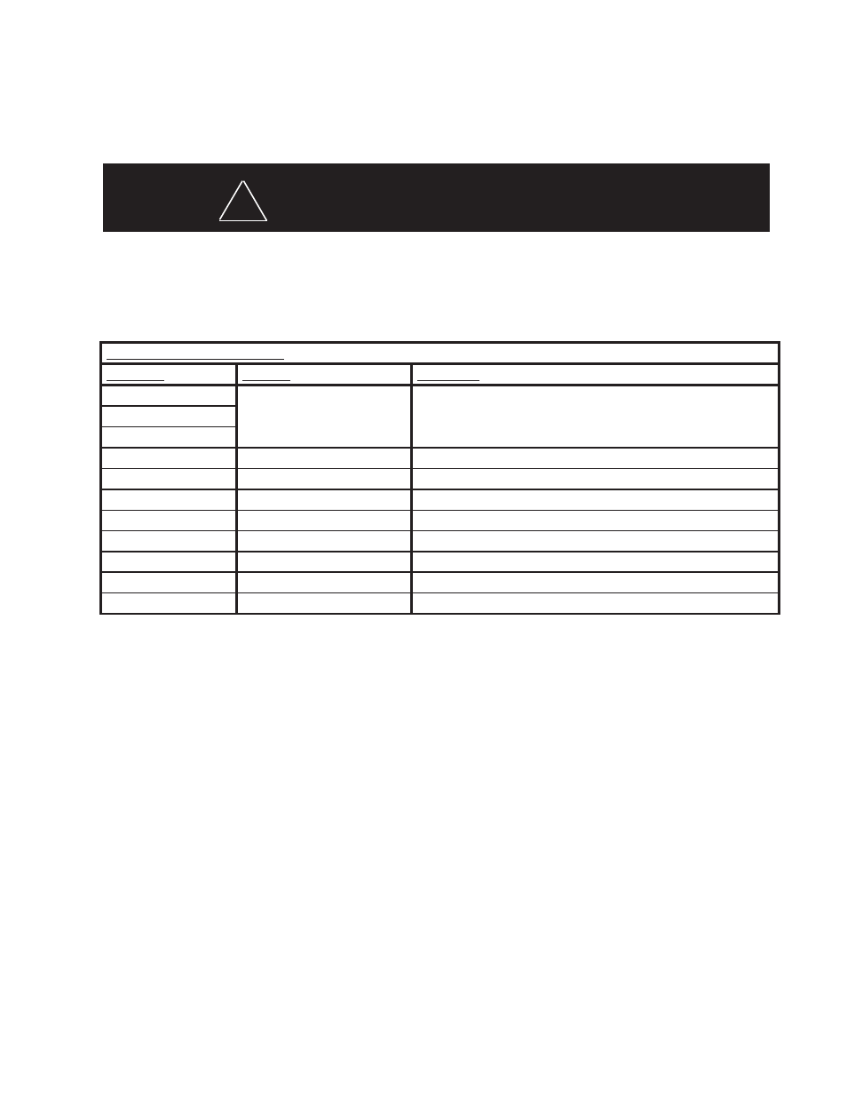
Table 1 - Control Wire Definitions - Ranger
TM
Note: All control inputs are +power enabled.
Control Input Function Definition
wire color
Function
Description
RED (16 GA)
GROUND
GROUND
RED / WHITE (16 GA)
BLUE (18 GA)
Take Down lights
Take Down Lights Steady Burn
ORANGE (18 GA)
PS Alley Light
PS Alley Steady Burn
YELLOW (18 GA)
DS Alley Light
DS Alley Steady Burn
BROWN (18 GA)
Front directional and corner lights Provides power for all front facing directional and corner light heads
VIOLET (18 GA)
Rear directional and corner lights Provides power for all rear facing directional and corner light heads
Flash Pattern Selection - Ranger
TM
The Pattern Selection is accomplished by setting of each light head individually.
1. Remove the upper lens clips using a flat blade screwdriver. (care should be given so that the lens gasket is not damaged during
lens removal.)
2. The light head PCB has two prongs facing forward on the top edge of each LED module. While under power, a flat blade screw-
driver or other metal object placed between these two prongs will change the pattern to the next setting. Each head will need to be
changed separately.
3. Once each head has been set to the desired flash pattern, re-install the upper lens and lens clips to the light bar.
Bars with STT option installed:
Stop Turn Tail lights are powered through a separate 3 wire cable.
1. Run wire for DS light head to turn signal LED light to junction for Driver side turn signal light on vehicle.
2. Run wire for PS light head to turn signal LED light to junction for Passenger side turn signal light on vehicl.e
3. Run wire for Stop signal to brake light switch on vehicle wiring harness.
This Product contains high intensity LED devices. To prevent eye damage, DO NOT
stare into light beam at close range.
wARNING!
!
Routing
Route the wiring cables into the engine or passenger compartment, taking care to use grommets and to apply sealant around openings
to keep water out. It is advisable to leave an extra loop of cable when installing the light bar to allow for future changes or reinstallations.
Connect the Red and Red/Whiite leads to a solid frame ground (earth), preferably, the (-) or ground (earth) side of the battery and bring
the other wires to the control head or switches. Connect the wires as directed by the wiring instructions on the cable.