Warning – Code 3 OsciLaser Rear Deck/Dash Mount User Manual
Page 3
3
anchor and protect all wiring. Fuses or circuit breakers should be located as close to the
power takeoff points as possible and properly sized to protect the wiring and devices.
Particular attention should be paid to the location and method of making electrical
connections and splices to protect these points from corrosion and loss of conductivity.
Ground terminations should only be made to substantial chassis components, preferably
directly to the vehicle battery. The user should install a fuse sized to approximately 125% of
the maximum Amp capacity in the supply line to protect against short circuits. For example, a
30 Amp fuse should carry a maximum of 24 Amps.
DO NOT USE 1/4" DIAMETER GLASS FUSES AS THEY ARE NOT SUITABLE FOR
CONTINUOUS DUTY IN SIZES ABOVE 15 AMPS.
Circuit breakers are very sensitive to high temperatures and will "false trip" when mounted in
hot environments or operated close to their capacity.
WARNING!
!
4
8
9
10
3
9
10
5
1
FIGURE 2
OLDM
FIGURE 1
5
OLRD
7
1
6
2
3
11
5
7
13
8
2
6
4
NOTE : All of the information listed in this
booklet must be given to the end user by
the installer.
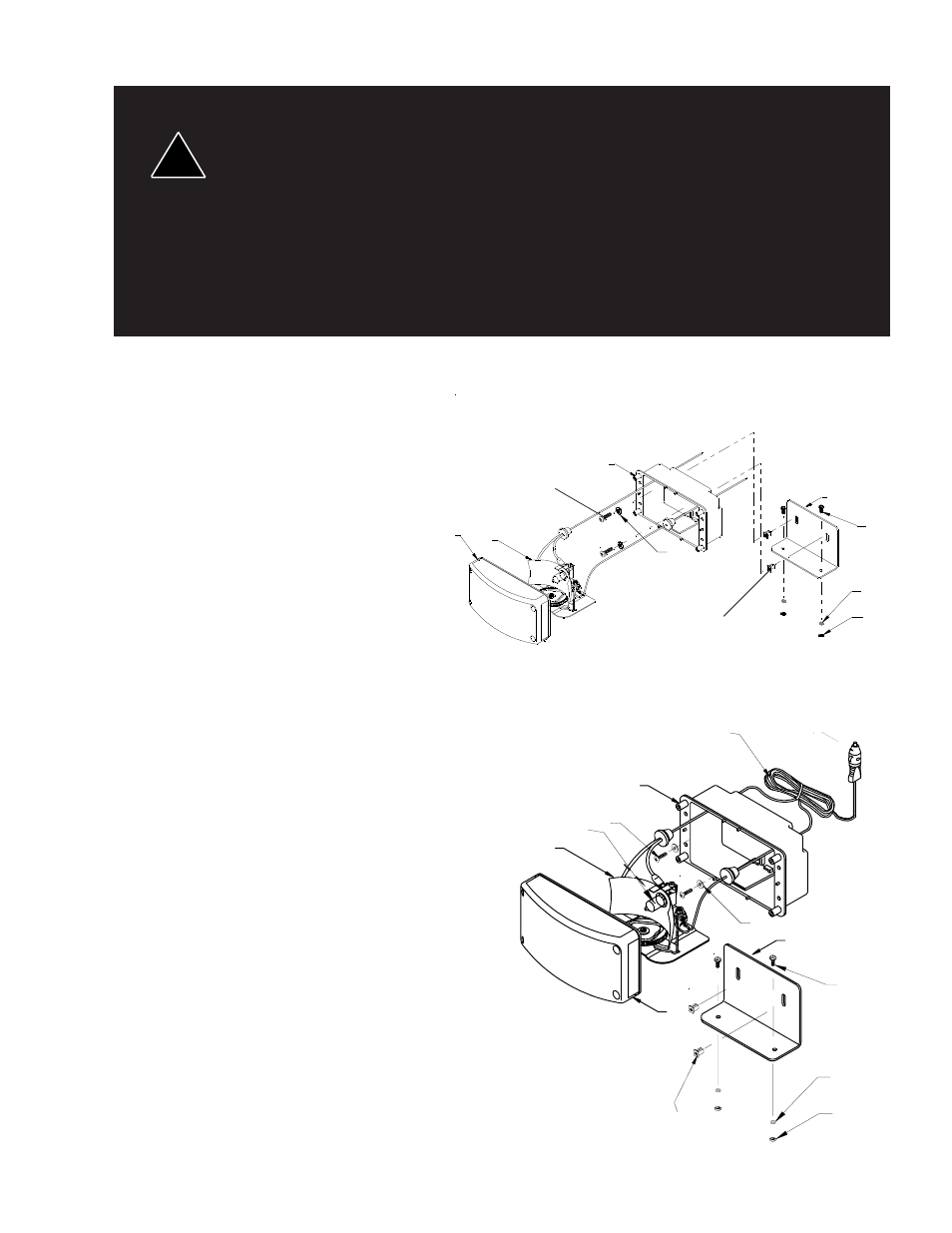
OLRD INSTALLATION:
Mounting the L Bracket
1) Choose a suitable location for mounting
the Oscilaser , Using the square
mounting holes in the bottom of the
bracket as a template, mark the mount-
ing hole positions. (NOTE: The bracket
bottom "L" can be turned either direction
based on mounting requirements.) Drill
one (5/16)" hole at each mark.
2) Using the supplied lockwashers, nuts,
and carriage bolts, mount the bracket to
the drilled holes. (See Figure 2.) Insure
that the fasteners are sufficiently tight.
Mounting the Oscilaser:
3) To install the Oscilaser to the "L"
Bracket, remove four lens screws and
pull lens from housing. Pull the Oscilaser
oscillating unit (Part #2) from housing.
4) Insert the supplied plastic inserts (Part
#7) into the back of the bracket. (Note:
push the inserts in from the side that the
light will be mounted on.)
5) Using the supplied screws and washers
(Parts #5 and #6, see Figure 1), attach
the housing to the inserts in the bracket.
Insure that the fasteners are sufficiently
tight.
6) Reassemble the Oscilaser, making sure
not to pinch the wires when tightening
the lens screws.
OLDM INSTALLATION:
The OLDM can be mounted with the "L"
Bracket in the same fashion as de-
scribed above or it can be mounted using
the adjustable bracket.
1) Assemble the Dash Mount bracket
according to Figure 2 or 3 per applicable
mounting.
2) Find a suitable flat mounting position for
the unit.
5
3
7
TM