Unpacking & pre-installation, General description, Specifications – Code 3 LED PriZm II Perimeter Lights User Manual
Page 2: Warning
The use of this or any warning device does not insure that all drivers can or will observe or react to an emergency
warning signal. Never take the right-of-way for granted. It is your responsibility to be sure you can proceed safely
before entering an intersection, driving against traffic, responding at a high rate of speed, or walking on or around
traffic lanes.
The effectiveness of this warning device is highly dependent upon correct mounting and wiring. Read and follow
the manufacturer’s instructions before installing or using this device. The vehicle operator should insure daily that
all features of the device operate correctly. In use, the vehicle operator should insure the projection of the warning
signal is not blocked by vehicle components (i.e. open trunks or compartment doors), people, vehicles, or other
obstructions.
This equipment is intended for use by authorized personnel only. It is the user’s responsibility to understand and
obey all laws regarding emergency warning devices. The user should check all applicable city, state and federal
laws and regulations.
Public Safety Equipment, Inc., assumes no liability for any loss resulting from the use of this warning device.
Proper installation is vital to the performance of this warning device and the safe operation of the emergency vehicle.
It is important to recognize that the operator of the emergency vehicle is under psychological and physiological
stress caused by the emergency situation. The warning device should be installed in such a manner as to: A) Not
reduce the output performance of the system; B) Place the controls within convenient reach of the operator so that
he can operate the system without losing eye contact with the roadway.
Emergency warning devices often require high electrical voltages and/or currents. Properly protect and use caution
around live electrical connections. Grounding or shorting of electrical connections can cause high current arcing,
which can cause personal injury and/or severe vehicle damage, including fire. Wait 10 minutes after turning off
the power from system before touching any internal components. Always wear hand and eye protection when
handling electrical components.
PROPER INSTALLATION COMBINED WITH OPERATOR TRAINING IN THE PROPER USE OF EMERGENCY
WARNING DEVICES IS ESSENTIAL TO INSURE THE SAFETY OF EMERGENCY PERSONNEL AND THE
PUBLIC.
WARNING
Unpacking & Pre-Installation
Carefully remove the light head from its protective packaging. Inspect the unit for transit damage. Report any
damage to the carrier and keep the shipping carton. Verify the contents of the package (refer to Table 3 and Fig-
ures 2 and 3). Test the lights before installation. To test, touch the black wire to ground and the red wire to 12 VDC.
If a problem occurs, contact the factory.
2
General Description
The PriZm II Perimeter lights are offered in sizes 3x7, 4x6 and 7x9. Both solid and multi-color are available.
Multi-color lights are “split” horizontally (left/right). The outer lens will be field replaceable, and will provide a
waterproof barrier via an interface with a field replaceable outer gasket. The units are surface-mounted, requir-
ing no recesses to be cut in the vehicles for normal mounting. Only a hole for wiring and small holes for mount-
ing screws will be required. The unit will be available with or without bezel, and they operate on 2 volts. The
solid color lights are offered in the following colors: Red, Blue, Amber, White and Green. Multi-colored light are
available in numerous configurations (refer to Table 3). Many flash patterns are offered, all between 75-150
fpm. The units also feature dimming, synchronization and independent on/off (certain models only).
!
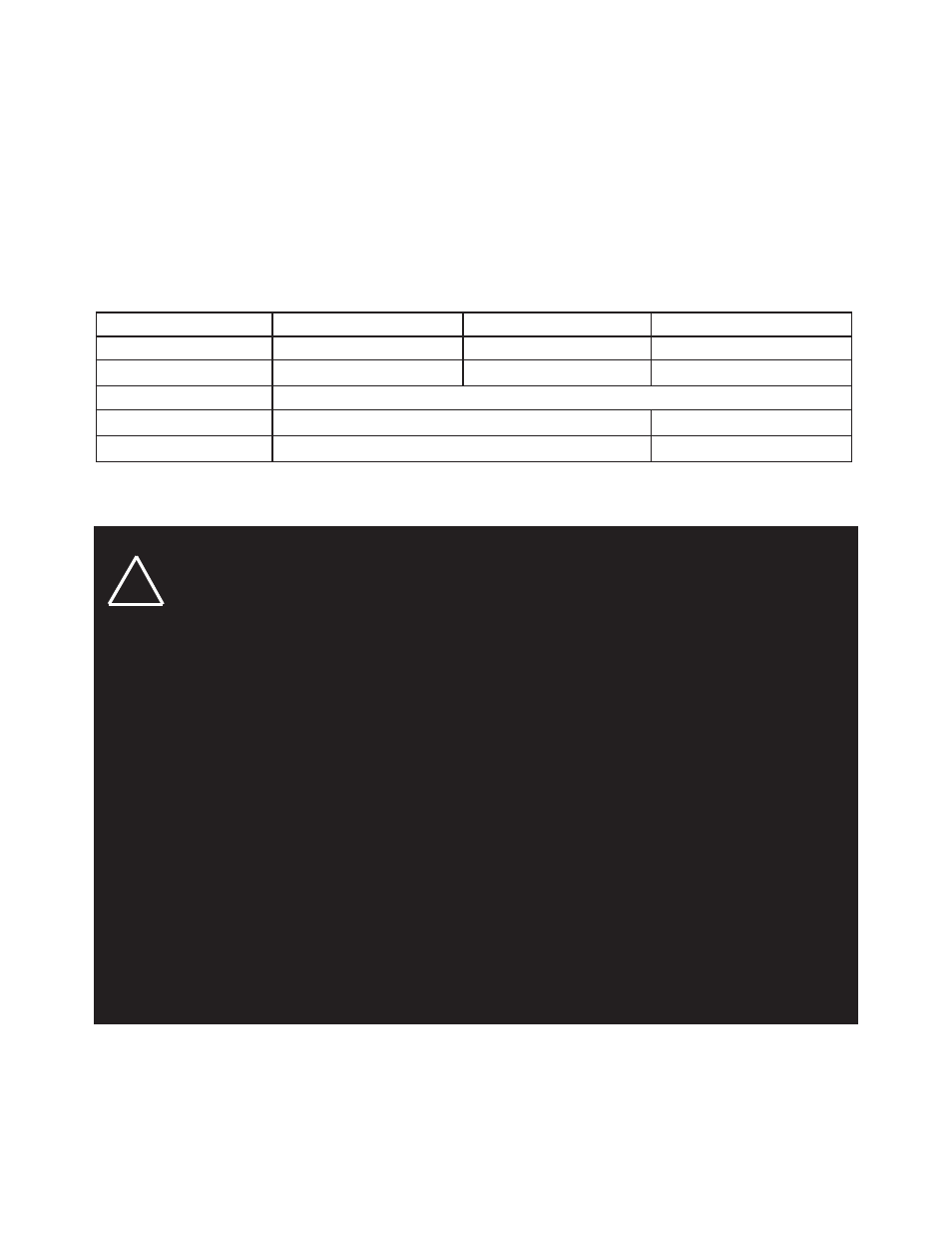
Specifications
3x7
4x6
7x9
Size
1.5” x 4.75” x 9.0” (w/ bezel)
1.5” x 6.0” x 8.5” (w/ bezel)
1.5” x 9.0” x 11.0” (w/ bezel)
Weight
1.0 lbs
1.1 lbs
2.25 lbs
Operating Voltage
11-15 Volts
Average Current Draw
1
0.6 (8 LEDs), 0.7 (12 LEDs)
1.6 (24 LEDs), 1.9 (36 LEDs)
Peak Current Draw
2
1.3 (8 LEDs), 1.6 (12 LEDs)
3.8 (24 LEDs), 4.6 (36 LEDs)
Note 1: At 12.8V, 78
O
F and using NFPA Quad Flash
Note 2: At 12.8V, 78
O
F