Code 3 for 2010 Tahoe User Manual
Page 2
2
!
Larger wires and tight connections will provide longer service life for components. For high current wires it is highly recom-
mended that terminal blocks or soldered connections be used with shrink tubing to protect the connections. Do not use
insulation displacement connectors (e.g. 3M® Scotchlock type connectors). Route wiring using grommets and sealant when
passing through compartment walls. Minimize the number of splices to reduce voltage drop. High ambient temperatures (e.g.
under-hood) will significantly reduce the current carrying capacity of wires, fuses, and circuit breakers. Use “SXL” type wire
in engine compartment. All wiring should conform to the minimum wire size and other recommendations of the manufacturer
and be protected from moving parts and hot surfaces. Looms, grommets, cable ties, and similar installation hardware should
be used to anchor and protect all wiring.
Particular attention should be paid to the location and method of making electrical connections and splices to protect these
points from corrosion and loss of conductivity. Ground terminations should only be made to substantial chassis components,
preferably directly to the vehicle battery.
The user should install a fuse sized to approximately 125% of the maximum Amp capacity in the supply line and each switched
circuit to protect against short circuits. For example, a 30 Amp fuse should carry a maximum of 24 Amps. DO NOT USE 1/4”
DIAMETER GLASS FUSES AS THEY ARE NOT SUITABLE FOR CONTINUOUS DUTY IN SIZES ABOVE 15 AMPS. Circuit
breakers are very sensitive to high temperatures and will “false trip” when mounted in hot environments or operated close to
their capacity. Fuses or circuit breakers should be located as close to the power takeoff points as possible and properly sized
to protect the wiring and devices.
WARNING
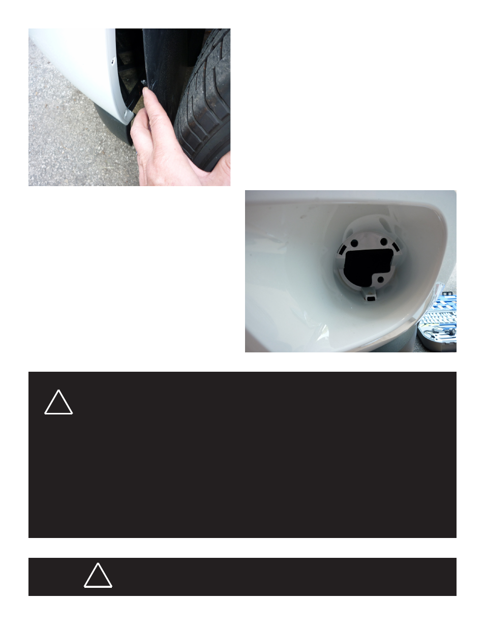
1. Remove Hex fastener at base of front wheel well
2. Pry loose the bottom push-in fastener from wheel
well cover
3. Pry loose the two side push-in fasteners from the
wheel well to gain access to rear of fog light mount-
ing area of vehicle (fig. 1)
4. Push out the fog light cover plate if installed to
reveal bracket mounting area (fig. 2)
5. Assemble PAR 36 unit as shown in exploded view
found on parts list. (fig. 4)
6. Place unit into fog light opening with the base tab
of assembly facing down
7. Snap bottom tab of bracket into center rectangular
hole and push bracket assembly vertical in opening
with threaded studs through top two mounting holes
on vehicle
Fig 1
Fig 2
WARNING
!
Any electronic device may create or be affected by electromagnetic interference. After installation of any electronic
device, operate all equipment simultaneously to insure that operation is free of interference.