Wiring instructions, Setting flash pattern: vari-flash (option), Flash patterns autodim: 99xxx series only – Code 3 90 Series Strobe Beacon User Manual
Page 4: Warning
4
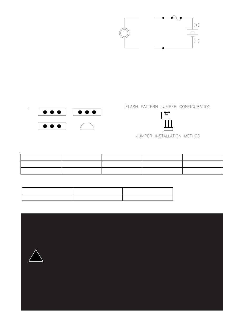
Wiring Instructions
The Series 90 Strobe Beacons are shipped fully tested and
ready for installation. Connect wiring as shown in Figure 2.
Use a 10 Amp fuse for circuit protection and #18 gauge or
larger wire. Grommets and sealant should be used to keep
water out of your vehicle.
Setting Flash Pattern: Vari-Flash (option)
To Select a flash pattern on the unit follow the directions provided below:
1. Turn power off and wait 10 minutes before opening the unit.
2. Remove lens and select the appropriate flash configuration. Use Figure 3 as a guide
3. Reassemble the lens.
Larger wires and tight connections will provide longer service life for components. For high current wires it is highly
recommended that terminal blocks or soldered connections be used
with shrink tubing to protect the connections.
Do not use insulation displacement connectors (e.g. 3M
®
Scotchlock type connectors). Route wiring using grommets
and sealant when passing through compartment walls. Minimize the number of splices to reduce voltage drop.
High ambient temperatures (e.g. under hood) will significantly reduce the current carrying capacity of wires, fuses,
and circuit breakers. Use "SXL" type wire in engine compartment. All wiring should conform to the minimum wire
size and other recommendations of the manufacturer and be protected from moving parts and hot surfaces. Looms,
grommets, cable ties, and similar installation hardware should be used to anchor and protect all wiring.
Fuses or circuit breakers should be located as close to the power takeoff points as possible and properly sized to
protect the wiring and devices. Particular attention should be paid to the location and method of making electrical
connections and splices to protect these points from corrosion and loss of conductivity. Ground terminations should
only be made to substantial chassis components, preferably directly to the vehicle battery.
The user should install a fuse sized to approximately 125% of the maximum Amp capacity in the supply line to protect
against short circuits. For example, a 30 Amp fuse should carry a maximum of 24 Amps. DO NOT USE 1/4"
DIAMETER GLASS FUSES AS THEY ARE NOT SUITABLE FOR CONTINUOUS DUTY IN SIZES ABOVE 15
AMPS. Circuit breakers are very sensitive to high temperatures and will "false trip" when mounted in hot
environments or operated close to their capacity.
Red
Wire
Strobe
Beacon
12/24
VDC
Black
Wire
FIGURE 2
10 A
Fuse
JP1
JP2
JP3
Q3
Flash Patterns
AutoDim: 99XXX Series Only
FIGURE 3
WARNING!
!
Jumper
Quad Flash
Double Flash
2, 4 Flash
2, 3, 4 Flash
JP1
2-3
2-3
1-2
1-2
JP2
1-2
2-3
2-3
1-2
Jumper
AutoDim Enabled
AutoDim Disabled
JP3
2-3
1-2