Salter Brecknell RD Series User Manual
Page 4
Power down the RD Series Remote Display. Remove the two screws holding the setup switch
cover located on the center of the back cover. Slide the switch to the left position for setup. Power
up the RD Series Remote Display. Power up your digital indicator. The RD Series Remote
Display will begin cycling through the possible combinations of baud rate, bits and parity. When
the configuration from your indicator is found, the RD Series Remote Display will show SET and
begin to operate. Slide the configuration switch to the right position and replace the cover and two
screws. Attach the rear cover.
2. Manual setup – Applies to RS232, RS0485 and Current Loop
If you want to set the baud rate/bits/parity manually in the RD Series Remote Display, power
down the unit. Remove the two screws holding the setup switch cover located on the center of the
back cover. Slide the switch to the left position for setup. Power up the RD Series Remote
Display. Watch the display begin cycling through the possible combinations of baud rate, bits and
parity. Wait until the desired baud rate and bit/parity combination is displayed. Immediately power
down the remote display to capture those settings. Slide the configuration switch to the right
position and replace the cover and two screws. Connect your indicator as shown above. Power
up the indicator and make sure it is operating properly and displaying weight. Power up the RD
Series Remote Display. Both your indicator and the remote display should be operating properly.
If not, retry the procedure or try the automatic procedure as outlined above.
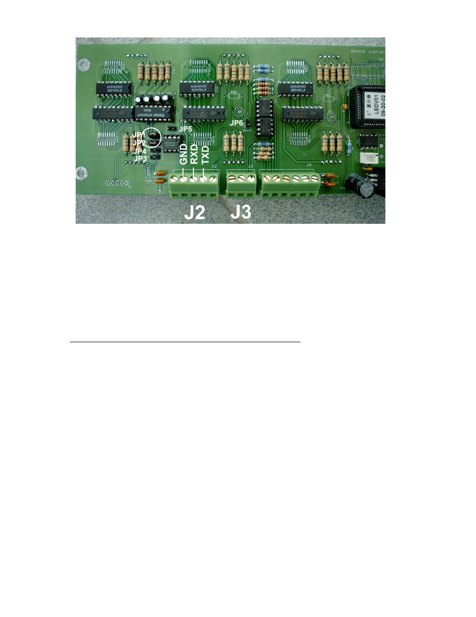
RD-2 2” remote RS232 connections