Making the connections – AVer CP150 user manual User Manual
Page 9
E-5
English
Deut
sch
Français
It
aliano
Esp
a
ñol
Č
esky
M
M
a
a
k
k
i
i
n
n
g
g
t
t
h
h
e
e
C
C
o
o
n
n
n
n
e
e
c
c
t
t
i
i
o
o
n
n
s
s
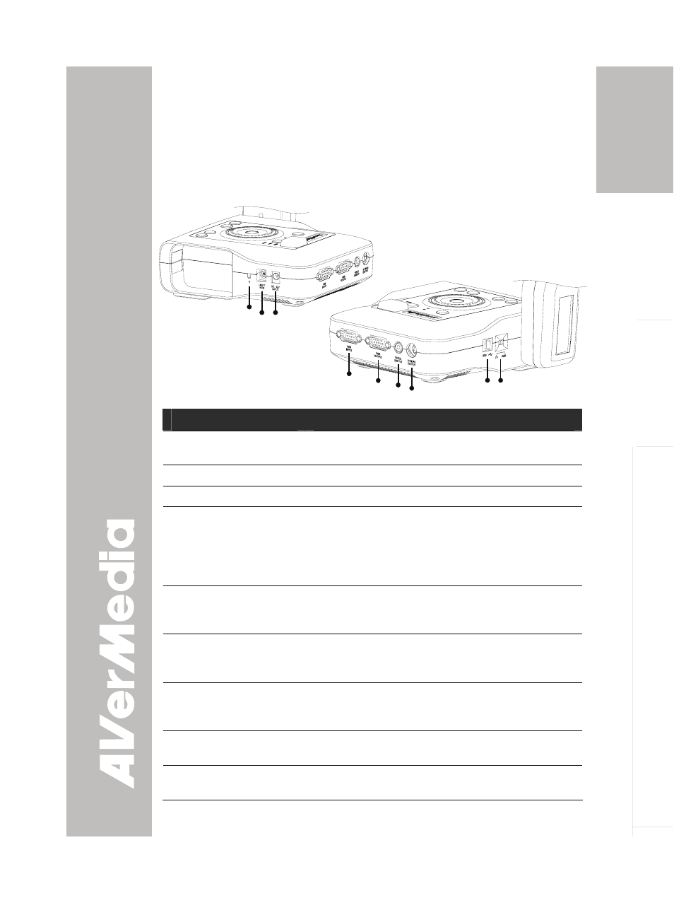
The ports on the rear, left and right panel of CP150 enable you to
connect the unit to a computer, graphics display monitor or LCD/DLP
projector, TV or other device. Illustrated below are the ports that are
located at the rear, left and right panel of CP150 with their corresponding
labels.
(2)(3)
(1)
Right Panel
(5) (6)(7)
(8)
(4)
(9)
Rear & Left Panel
Port
Description
(1) Antitheft Slot
Attach a Kensington compatible security lock or
antitheft device.
(2) Light Box
Plug the optional light box into this port.
(3) DC 12V Input
Connect the power adapter into this port.
(4) RGB INPUT
Input the signal from a computer or other
sources and pass it through to the RGB Output
port only.
Connect this port to the VGA output port of the
computer.
(5) RGB OUTPUT
Output the signal from the camera, RGB input
port, or the captured images from the memory on
a VGA/Mac monitor or LCD/DLP projector.
(6) VIDEO OUTPUT
(RCA/Composite)
Output the signal from the camera or the
captured images from the memory on TV or
Video equipment.
(7) S-VIDEO OUTPUT
Output the signal from the camera or the
captured images from the memory on TV or
Video equipment.
(8) USB
Use CP150 as a USB Camera or transfer the
captured images from CP150 memory to PC.
(9) TV-RGB switch
Switch to output display video either from Video,
S-VIDEO, or RGB output port.