Installation manual, 34 4 a a a b – Alumax L-210 User Manual
Page 16
INSTALLATION MANUAL
16
2
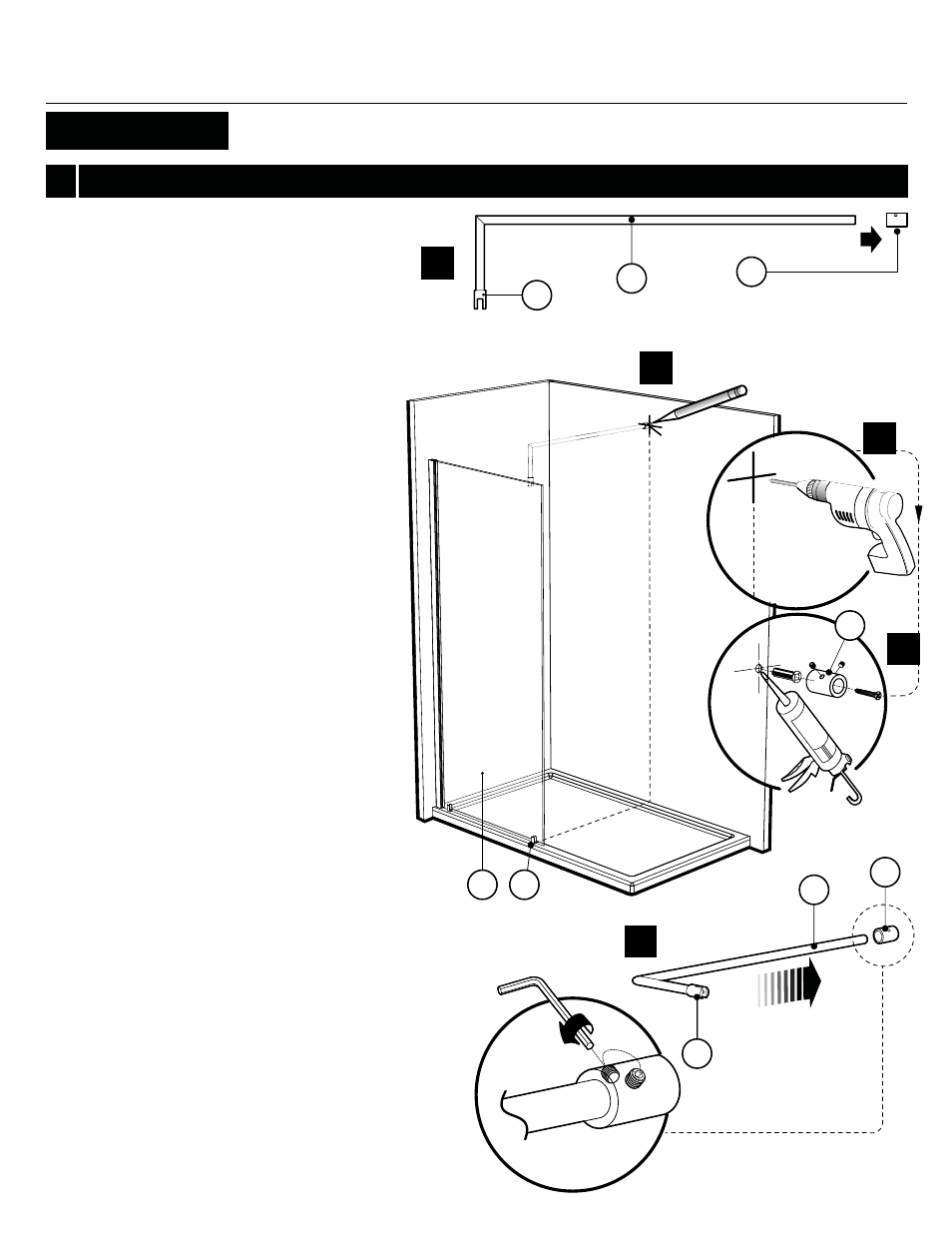
SUPPORT BAR INSTALLATION
2a. Take apart the end component (A) of the support
bar (4) with the provided Allen Key.
2b.
Transfer the position of the bottom clip (3) to the
back wall. At 82”
(208cm) from the threshold mark
the position (center of the cylinder ) for the support
bar wall end component.
2c.
Drill the back wall using a Ø1/4”drill bit.
2d.
Apply a bead of silicone in the hole and insert the
wall plug.
Proceed to fasten the wall end components (A) onto
the wall.
2e. To ease subsequent installation on the front panel (1.1).
Insert bar (4) in the wall end component (A) on a
horizontal plane as shown.
Tighten the set screws.
Wall end component
MIN
82”
(208cm)
|
MAX.
82
1/4”
(209cm)
DIS
TANCE FROM
TO
P O
F THRESHOLD
TO CENTER O
F
W
AL
L END COMPONENT
3
4
4
A
A
A
B
2a
2b
2e
2c
2d
1.1
B
100X, 210X, 210TBX