Assembly instructions – Craftsman 247.885680 User Manual
Page 7
Attention! The text in this document has been recognized automatically. To view the original document, you can use the "Original mode".
ASSEMBLY INSTRUCTIONS
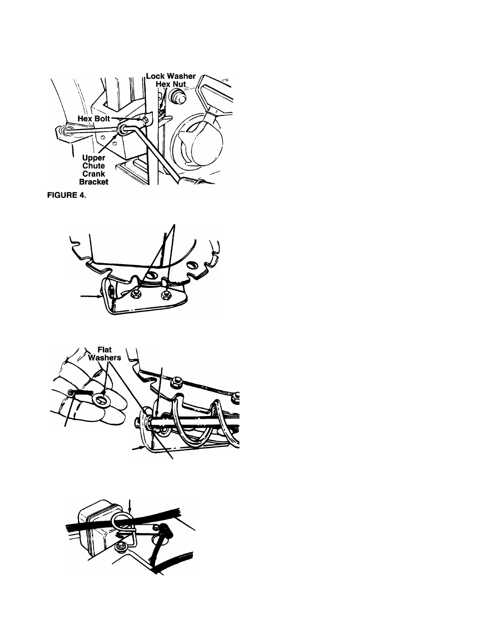
ATTACHING THE CHUTE CRANK (Hardware C)
•
Insert hex bolt through the upper chute crank
— bracket. See figure 4.
• Place the hex bolt into the hole provided in the left
handle. Secure with lock washer and hex nut. Do
not tighten until after attaching the other end of the
chute crank.
Lower
Chute
Crank
Bracket
Carriage
Bolts
Hex Lock Nuts
• Loosen the carriage bolts and hex lock nuts which
secure the lower chute crank bracket to the exten
sion on the left side of the chute assembly. See
— figure 5.
FIGURE 5.
Chute
Crank
Cotter
Pin
Lower
Chute Crank
Bracket
FIGURE 6.
Plastic
Bushing
Place one flat washer on the end of the chute
crank, then insert the end of the crank into the hole
in the plastic bushing in the chute crank bracket.
See figure
6
. Place the other flat washer on the end
of the chute crank, and insert cotter pin into hole in
the end of crank. Secure by bending the ends of
cotter pin in opposite directions.
Adjust the chute bracket so that the spiral on the
chute crank fully engages the teeth on the chute
assembly. Tighten the nuts on the lower chute
crank bracket securely. Tighten the hex bolt and
nut on the upper chute crank bracket on the
handle.
Cable
Guide
• Slip the cables that run from the handle panel to
the chute into the cable guide located on top of the
— engine. See figure 7.
FIGURE 7.