Changing the friction wheel rubber, Traction drive clutch adjustment, Service & adjustment – Craftsman 247.885680 User Manual
Page 19
Attention! The text in this document has been recognized automatically. To view the original document, you can use the "Original mode".
SERVICE & ADJUSTMENT
• If a replacement drive belt is needed, follow
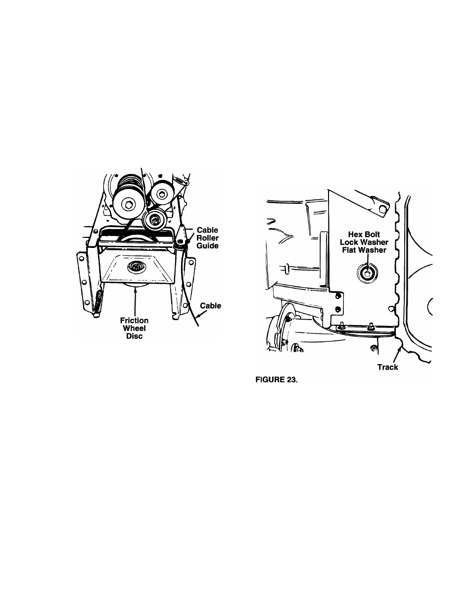
previous instructions. Pull idler pulley up and lift
belt off friction wheel disc. See figure 22.
Reassemble in reverse order.
NOTE:
When reassembling the two halves of the unit,
the auger drive cable must be routed through the
cable roller guides as shown in figure 22.
Idler
Pulley
FIGURE 22.
•
Remove the six screws from the friction wheel
assembly (three from each side). Remove the fric
tion wheel rubber from between the friction wheel
plate.
• Reassemble new friction wheel rubber to the fric
tion wheel assembly, tightening the six screws in
rotation and with equal force.
• Slide the friction wheel assembly up onto the shift
mechanism as shown in figure 24, and slide the
gear shaft back into the unit. Reassemble in
reverse order.
N
CHANGING THE FRICTION WHEEL
RUBBER
The rubber on the friction wheel is subject to wear
and should be checked after 25 hours of operation,
and periodically thereafter. Replace the friction wheel
rubber if any signs of wear or cracking are found.
• Drain the gasoline from the snow thrower, or place
a piece of plastic under the gas cap.
• Tip the snow thrower up and forward, so that it
rests on the housing.
• Remove four self-tapping screws from the frame
cover underneath the snow thrower.
• Remove the gear shaft from the unit by removing
the bolts, lock washers and flat washers from each
side of the frame. See figure 23. Hold the friction
wheel assembly, and slide the gear shaft out of the
unit toward the right hand side. Refer to figure 24.
TRACTION DRIVE CLUTCH ADJUSTMENT
Refer to the Final Adjustment section of the Assembly
Instructions to adjust the traction drive clutch. If you
are uncertain that you have reached the correct
adjustment, the adjustment can be physically checked
as follows.
With the snow thrower tipped fonward (be certain to
drain the gasoline or place plastic film under the gas
cap if the snow thrower has already been operated),
remove the frame cover underneath the snow thrower
by removing four self-tapping screws. With the trac
tion drive clutch released, there must be clearance
between the friction wheel and the drive plate in all
positions of the shift lever. With the traction drive
clutch engaged, the friction wheel must contact the
drive plate. See figure 24.
19