Operation – Craftsman 247.885680 User Manual
Page 11
Attention! The text in this document has been recognized automatically. To view the original document, you can use the "Original mode".
OPERATION
TRACTION DRIVE/AUGER CLUTCH LOCK
(See figure 12)
The traction drive clutch is located on the right handle.
Squeeze the traction drive clutch to engage the wheel
drive. Release to stop.
This same lever also locks the auger clutch so you
can turn the chute crank without interrupting the snow
throwing process. If the auger drive clutch is engaged
with the traction drive clutch engaged, the operator
can release the auger drive clutch (on the left handle)
and the augers will remain engaged. Release the
traction drive clutch to stop both the augers and wheel
drive
(auger drive ciutch must aiso be released).
CHUTE CRANK (See figure 12)
The chute crank is located on left hand side of the
snow thrower.
To change the direction in which snow is thrown, turn
chute crank as follows:
1. Crank clockwise to discharge to the left.
2. Crank counterclockwise to discharge to the right.
THROTTLE CONTROL (See figure 14)
The throttle control is located on the engine. It regu
lates the speed of the engine.
LEFT AND RIGHT TRACK CONTROLS
The left and right track controls are located on the
underside of the handles and are used to assist in
steering your snow thrower. See figure
12
. Squeeze
the right track control when turning right, squeeze the
left control when turning left. Operate your snow
thrower in open areas until you become familiar with
these controls.
CHUTE TILT CONTROL
The distance snow is thrown can be adjusted by
adjusting the angle of the chute assembly. Move the
chute tilt control forward to decrease the distance,
toward the rear to increase. See figure 12.
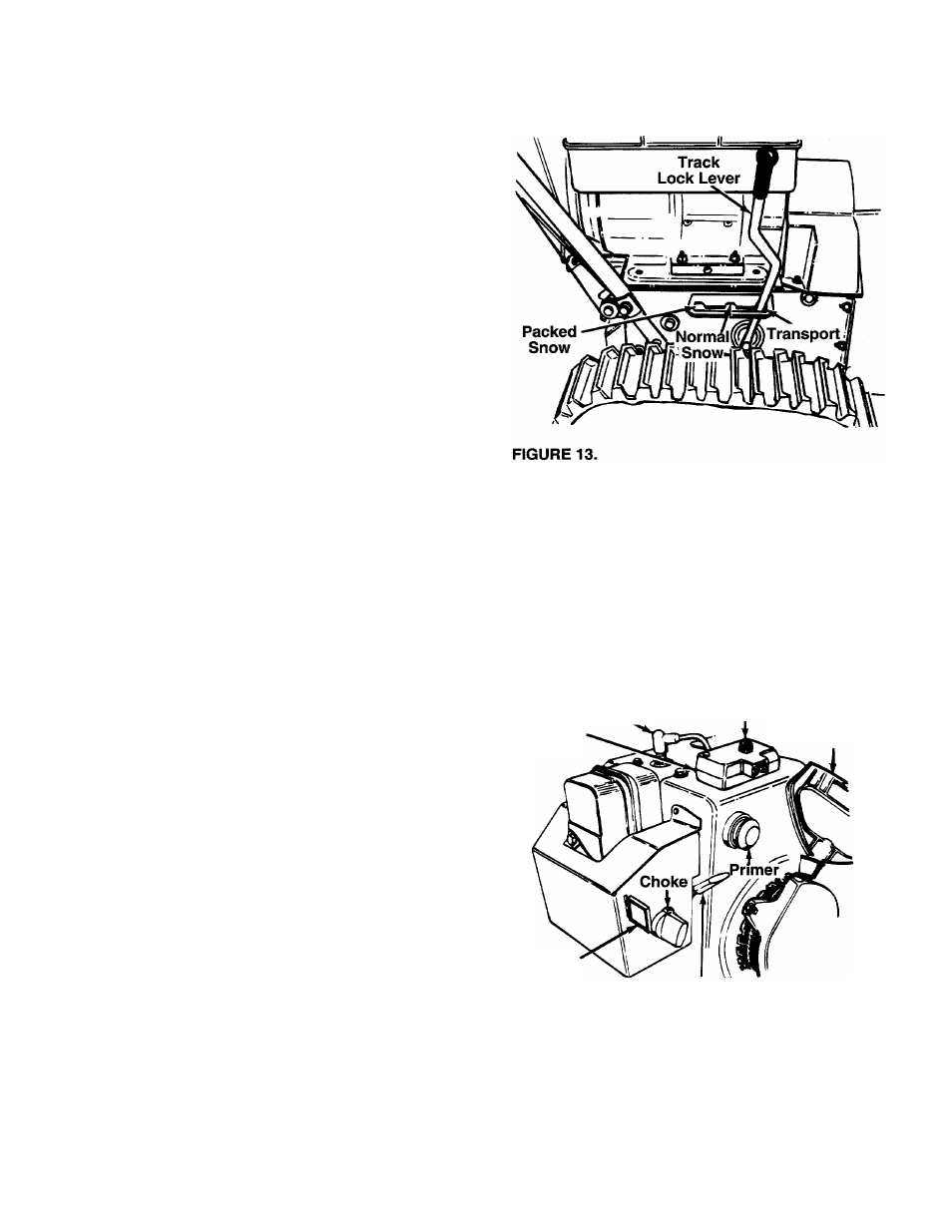
TRACK LOCK LEVER
The track lock lever is located on the right side of the
snow thrower and is used to select the position of the
housing and the method of track operation. See figure
13. Move the lever to the right, then forward or back
ward to one of the three positions.
Transport
—Raises the front end of the snow thrower
for easy transport. May also be used on gravel drive
ways to clear snow and leave gravel undisturbed.
Normal Snow
—Allows the tracks to be suspended
independently for continuous ground contact.
Packed Snow
—Locks the front end of the snow
thrower down to the ground for hard-packed or icy
snow conditions.
SAFETY IGNITION SWITCH (See figure 14)
The ignition key must be inserted in the switch before
the unit will start. Remove the ignition key when snow
thrower is not in use.
Spark
Plug
Starter
Button
Switch
Box
Rope Starter
Handle
Ignition
Key
FIGURE 14.
Throttle
Control
HEAD LAMP (8 H.P. Only)
The head lamp is on whenever the engine is running.
11