Craftsman 536.885210 User Manual
Page 13
Attention! The text in this document has been recognized automatically. To view the original document, you can use the "Original mode".
• Remove the gas cap.
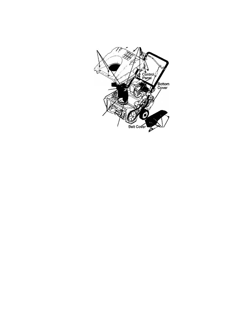
• Remove the two bolts and nuts from the
front lip of the top cover. Use a flat head
screwdriver and a 3/8" wrench. See figure
on this page.
• Remove the bolt from the front right side.
Use a 5/16“ and 3/8" wrench.
• Remove the four screws on the left side
of the top cover. Use a large flat head
screwdriver. See figure on this page.
• Remove the bolt from the front left side.
Use a 5/16" and 3/8“ wrench.
• Remove the four screws on the right side
of the top cover. Use a large flat head
screwdriver. See figure on this page.
• Remove the three screws from the top
portion of the control panel. Use a large
flat head screwdriver.
• Carefully pull up on the rear of top cover
making sure to clear gas tank.
• Carefully lift top cover over the three bolts
holding the lower chute to the chute ring.
NOTE:
This area was designed to have
a tight fit, it will be necessary to rock top
cover carefully over these bolts.
• Remove top cover.
• Reinstall in reverse order.
TO REMOVE BELT COVER
• Follow these steps from operator's
position.
• Remove the four bolts and nuts holding
the belt cover to the auger housing. Use
a 5/16" and 3/8" wrench.
• Remove the two screws holding the belt
cover to the top cover. Use a large flat
head screwdriver.
NOTE:
If the top cover
is already removed, omit this step.
• Remove the one screw holding the belt
cover to the bottom cover. Use a large
flat head screwdriver.
• Grasp the bottom portion of the belt cover
and pull down and out to remove.
• Reinstall in reverse order.
_ ,. . .
_
Screws to be
Bolts to be Top Cover
removed from Top
removed from / _____Xover
Top Cover
Discharge'
Chute
T-Knob and
Fasteners
Lower Chute
Bolts to be^
removed from
Belt Cover
Scmws
to be
removed
from Belt
Cover
TO ADJUST BRAKE PAD
The brake pad is adjusted at the factory and no
periodic adjustment is necessary.
IMPORTANT: Adjustment should only be
made to the brake if the brake pad has
become loose or has been removed. To
adjust proceed as follows:
NOTE: See figure on next page for proper
location of brake pad.
• Turn engine off.
• Remove belt cover. See To Remove Belt
Cover paragraph on this page.
• Remove the top cover. See To Remove
Top Cover instructions on page 12-13.
NOTE: Make sure the belt is in proper
position. See To Replace the Drive Belt
paragraph on page 14.
• Tie the control bail to the upper handle
with a piece of string. NOTE: This will
engage the pulley and belt system.
• Using a 7/16 wrench, 7/16 socket, and a
rächet loosen screw and nut on brake
pad. See first figure on page 14 for
location of screw and nut.
• Adjust brake pad up or down to have a
1/8" gap between the bottom of the brake
pad and the belt.
• Tighten screw and nut.
13