Assembly, Assembly cont – Craftsman 118.22000 User Manual
Page 9
Attention! The text in this document has been recognized automatically. To view the original document, you can use the "Original mode".
ASSEMBLY
MOUNTING LASER SYSTEM
1. Locate laser package and find the
following parts as shown in (Fig. 14):
a) Laser light system.
b) Two 6/32 screws with washers.
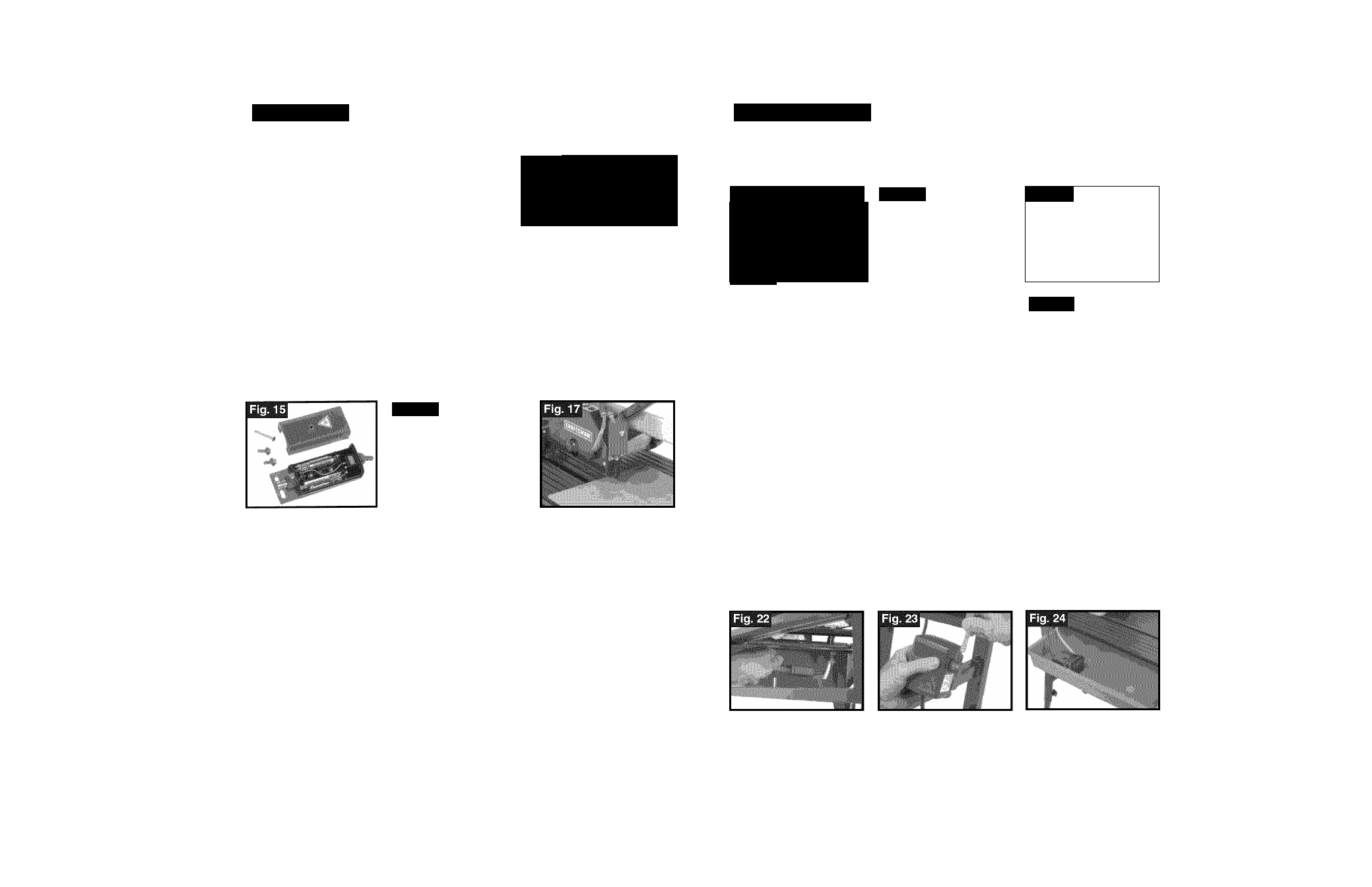
2. Loosen bolt and remove cover. Install two AAA
batteries (Fig.15), making sure both terminals are
positioned correctly as the marks on the cover show, then replace cover.
3. Screw laser system onto blade guard (Fig. 16).
4. Mark a cut line on a piece of scrap tile. Turn on the laser and align the laser with
the cut mark by loosening the bottom screw on the laser system (Fig. 17).
5. Cut the tile, paying attention to the position of the blade relative to the laser beam.
6
. Laser beam can be adjusted to the cut line.
7. Repeat Steps 4 through
6
until laser is properly adjusted, then tighten bottom
screw.
______ mM
NOTE: To avoid corrosion, remove the batteries when iaser system is not
being used.
Fig. 16
iNSTALLING THE BLADE
AWARNING
: Disconnect the power suppiy before instaiiing or making
adjustments to the biade.
Fig. 18
1
. FIRST,
to disconnect the water supply, press the blue ring and pull out the water
supply tube from the inlet connection on the blade guard (Fig. 18).
2.
NEXT,
remove the blade guard by removing the two securing screws, (Fig. 19).
3.
REMOVE
blade securing nut and outer flange from shaft. Place blade onto
shaft.
Directional arrows on blade
MUST
line up with
directional arrow on blade guard, so that material
to be cut is against the direction of rotation.
Re-install outer flange and nut (Fig. 20).
4.
TIGHTEN
by using the hexagonal wrench to turn the
blade-securing nut counter clockwise, and the motor
shaft securing wrench to hold the shaft stationary
(Fig. 20a).
16
ASSEMBLY cont.
INSTALLING THE BLADE cont.
5.
REPLACE
blade guard with the two securing screws.
6
.
RE-ATTACH
water supply tube to the inlet connection.
Fig. 19
I "
w
mm
A
Fig. 20
Fig. 20a
RIP/MITER GUIDE INSTALLATION
1. To install the rip/miter guide, slide aluminum arm of
rip/miter guide into the groove in the fence on saw
table (Fig 21).
2. The rip miter/guide can be made stationary by
tightening the screw and butterfly knob located on
the arm of the rip/miter guide.
WATER PUMP SETUP AND CONNECTION
Fig. 21
■
AWARNING:T
o
prevent the possibility of electrical shock, the tile saw
must be unplugged when connecting water pump.
Fig. 21a
—
1. Check to be certain that the water supply tube is
connected to the inlet connection on the blade guard
(Fig.
18).
2. T
o
connect the water pump power cord, locate the
black cover box under the table. Loosen butterfly
knob and remove black cover box (Fig. 21 a). Plug in
water pump cord, making sure fit is secure. (Fig. 22)
Replace black cover box and re-tighten butterfly knob.
3. Connect tube under table to water pump discharge fitting (Fig. 23).
4. Fit water pump into housing in water tray, making certain pump discharge fitting
aligns with cutout in tray housing (Fig. 24)
A
CAUTION: To prevent the possibility of electric shock, use only Sears
qualified replacement parts.
17
2
-
2-06