Parts & features – Craftsman 921.153101 User Manual
Page 5
Attention! The text in this document has been recognized automatically. To view the original document, you can use the "Original mode".
Parts & Features
Sea figures below for rsferance.
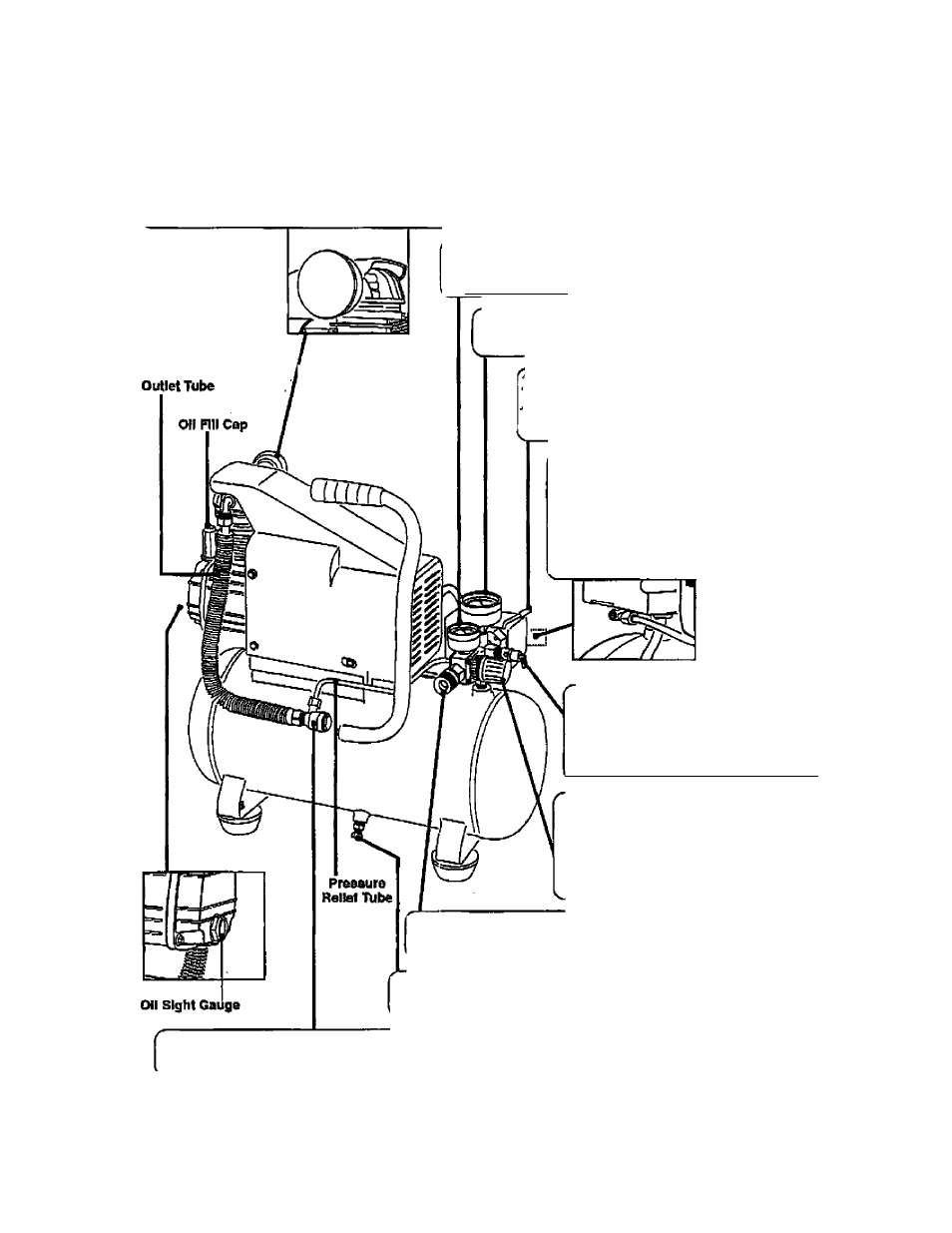
Air Intake Filter
Provides clean air to the pump and must always be kept free of debns. Check on a daily basis or before each use.
Regulator Gauge
Indicates the outgoing air pressure to the tool and Is controlled
by the regulator.
_____
Tank Pressure Gauge
Indicates the reserve air pressure in the tank.
Pressure dwitch
...
This controls the power to the motor apd-alra tHe.'-:-
cut-in/cut-out pressure settings. This switch sst^e'
as the Auto-On/Off positions for the unit.
Pressure Relief Valve
The pressure relief! valve located on the
side of the pressure sviritch, is designed to
automatically release compressed air when
the air compressor reaches oit-out pressure.
The reieased air shoidd only esc^s
momentarily and №e valve should then dose.'
Tank Safety Valve
Used to allow excess tank pressure to
escape into the atmosphere. This valve
should only open when the tank pressure
^ is above the maximum rated pressure.
RMUIator
Tne air pressure coming from the air tank is
controlled by the regulator To increase the
pressure turn the knob clockwise and to
decrease the pressure turn the knob ■
counterclockwise.
Quick Connect
Offers a quick release feature for attaching and removing the air hose.
Tank Drain Va^e
Used to drain condensation from the air tank. Located at bottom of tank: :
Check Valve
When the pump is not in operation the valve closes to retain air pressure insido the tank. An internal component.