Craftsman 315.214770 User Manual
Page 17
Attention! The text in this document has been recognized automatically. To view the original document, you can use the "Original mode".
I
J
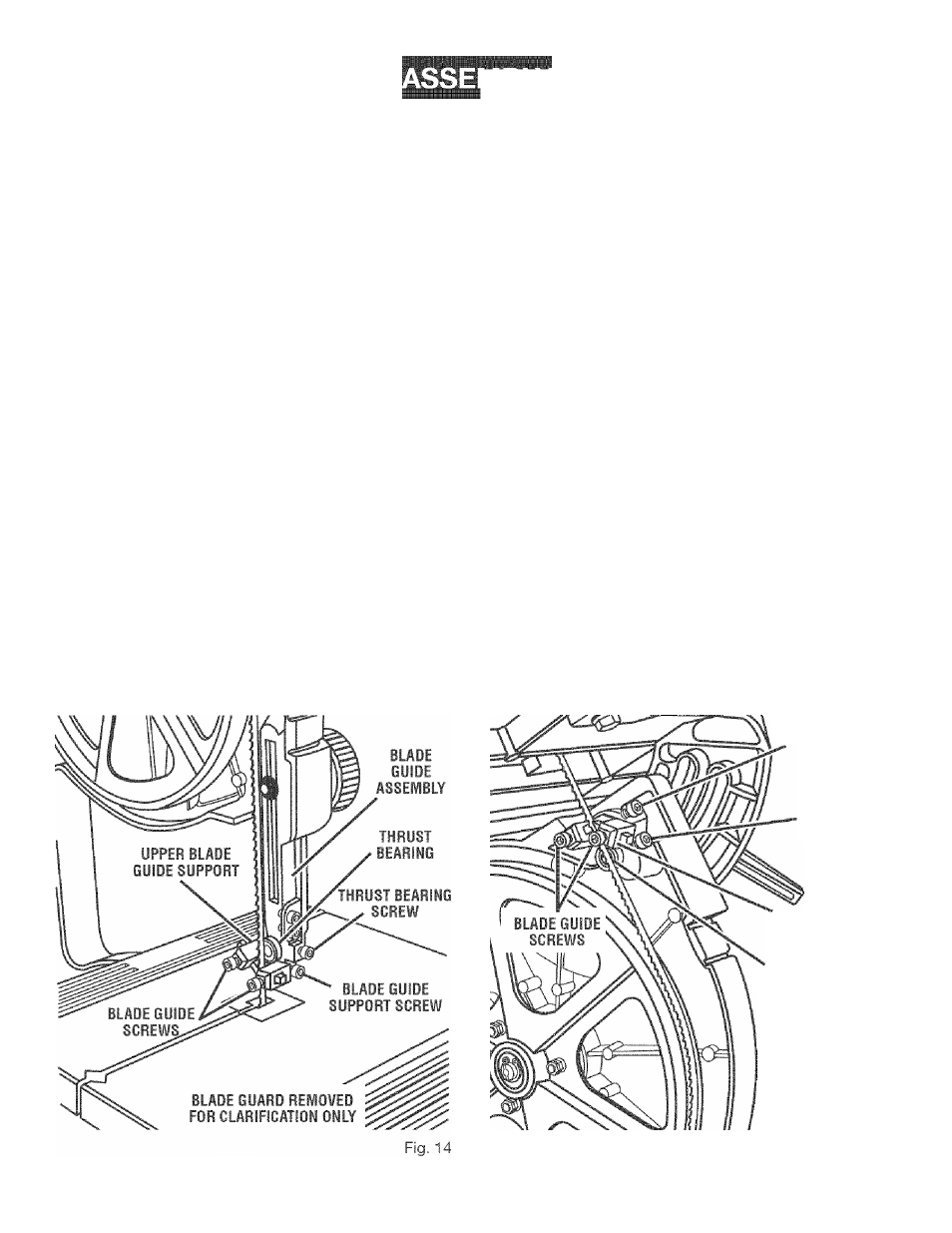
ADJUSTING THRUST BEARINGS, BLADE
GUIDE SUPPORT, AND BLADE GUIDES
See Figures 14 - 16.
A
WARNING: Never operate saw without blade guard
secured in place. To do so could result in possible
serious personal injury.
The upper and lower blade guides and thrust bearings
support the band saw blade during cutting operations.
The adjustment of the guides and bearings should be
checked whenever a different
blade is installed.
To Adjust Thrust Bearings:
The thrust bearings support the back edge of the blade
during
cutting. The blade should not
contact the thrust
bearings when you stop cutting. It
is
important that both
upper and lower thrust bearings be adjusted
equally.
NOTE:
The thrust bearing screw
is
the upper cap screw
located
on the right side of the blade guide assembly. It is
the lower cap screw on the right side of the saw
housing
below the saw
table
for the
lower
bearing.
■ Remove the blade guard by loosening the two set
screws with the 4 mm hex key.
■ Turn the lock
lever counterclockwise
to unlock the
blade guide assembly.
Turning
the blade guide knob
(clockwise raises the blade guide
assembly,
counter
clockwise lowers it), position the
blade
guide assembly
about halfway between the saw
table
and saw housing.
Retighten the lock lever.
■ Adjust the
thrust bearings
first.
Using the 4 mm hex
key,
loosen
the thrust bearing screw.
■ Move the thrust bearing to
within
1/64 in. of the blade.
Tighten the thrust bearing screw securely. Repeat this
procedure on the lower thrust bearing located
below
the saw table.
■ Replace the blade guard if no additional adjustments
are to be made.
To Adjust Blade Guide Support:
■ Remove the
blade
guard by loosening the two set
screws with the 4
mm
hex key.
■ Adjust
the position of the blade
guide
assembly.
Loosen the bottom screw on the right side of the blade
guide assembly
using
the 4 mm hex key.
■ Slide the upper
blade
guide support on the shaft until
the front edge of the blade guides
are about
1/64 in.
behind
the gullet
of the
blade.
Tighten the screw se
curely. Repeat this procedure for the lower blade guide
support.
■ Replace
the blade guard if no
additional
adjustments
are to be made.
NOTE: The lower blade guide support screw is
the
top
screw located on the right of the saw housing under
the table.
BLADE GUIDE
SUPPORT SCREW
THRUST
BEARING
SCREW
LOWER BLADE
GUIDE SUPPORT
THRUST BEARING
Fig. 15
17