Specifications – Sony MRD-D1 User Manual
Page 15
Attention! The text in this document has been recognized automatically. To view the original document, you can use the "Original mode".
Specifications
General
Size (H/W/D)
Mass
Power
Performance
Signal Inputs
Signal Outputs
RF carriers
RF Power Output
Antenna Isolation
Video Performance
Signal to Noise Ratio
Input Signal Level
Controls and Indicators
172
X
140
X
51 mm (6.8 x 5.5
x
2.0 in.)
1.19 kg (2 lbs, 10 oz.)
Transformer Input: 115 VAC, 60 Hz
Transformer Output: 12 VAC, 60 Hz
Consumption:
7 watts, typical
1 for CATV or Antenna
2 for video devices such as satellite receiver, VCR
or laserdisc player
5 for connecting to main TV, input to VCR and up
to 3 remote TVs
Note:
All outputs support IR operation of remote
devices when cormected to a target assembly.
Stability ±1 kHz
Frequency ranges: UHF channels 14 to 35
CATV channels 54 to 86
Charmel width: 6.0 MHz
Audio offset:
4.5 MHz
Sidebands:
Double
Modulator: 12.0 dBmV nominal (4000 pvolts)
15.5 dBmV maximum (5670 pvolts)
Greater than 60 dB
Differential Gain:
4%, typical
Differential Phase error: 4°, typical
45 dB, typical
Video: 1.0 volt peak to peak into 75 Q
Audio: 2.8 volt peak to peak into 47 kQ
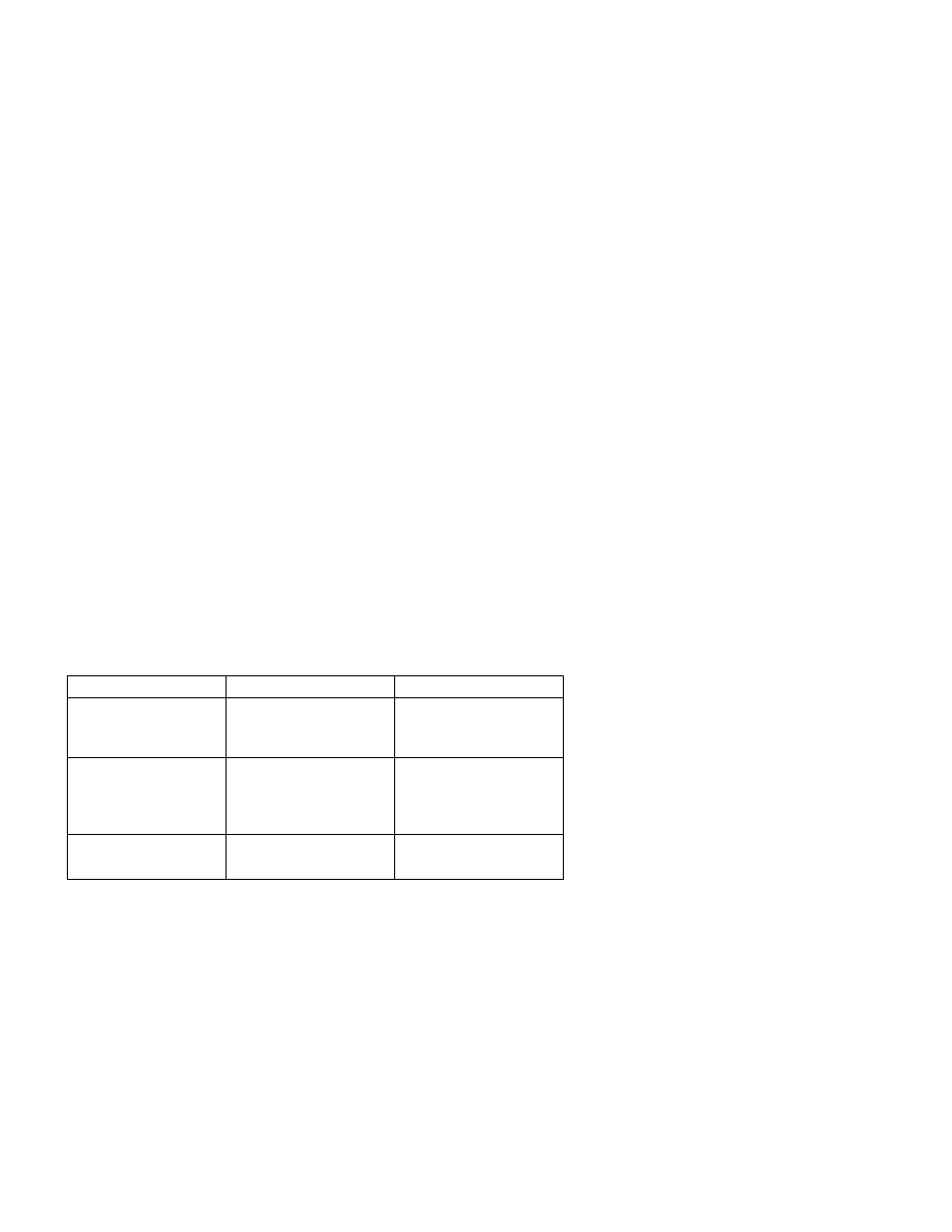
Function
Control/Indicator Type
Purpose
Output Channel Select
Four rotary indicators:
one (1) pair for each
output channel.
Select output channel.
Power On/Off
Green LED Indicator
a) Confirms power
applied.
b) Blinks to aid channel
selector positioning.
IR System Enabled
Red LED Indicator
a) Confirms IR repeater
system enabled.
15