System wiring diagram, 12 pin main harness – Crimestopper Security Products CS-865RKE User Manual
Page 8
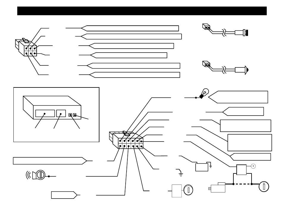
SYSTEM WIRING DIAGRAM
2nd Time for 2-Step Unlock
Press UNLOCK Button a
FUSE
BOX
+
BATTERY
IGN
SW.
Parking Lights
-
ORANGE
WHITE / RED
BLUE / WHITE
BLACK / YELLOW
WHITE/BLACK
RED
BLACK
YELLOW
GREEN
BROWN/WHITE
GRAY
(-) AUX. OUTPUT #3
+12V or (-) Neg. Dome Light
Output. (On-board 10A Relay)
(-) Passenger Unlock Ouput:
(-) AUX. OUTPUT #2
85
86
30
87A
CUT
START WIRE
STARTER
OPTIONAL
STARTER DISABLE WIRING
+12V or (-) Parking Light Output
(-) Negative Armed Output
(Relay not included)
+12V Power Input
Chassis Ground
IGN
SW.
+12V Ignition Input
NOT USED
(-) Negative Horn Output
(-) Negative Trunk Pop Output (AUX. 1)
12 PIN MAIN
HARNESS
6 PIN DOOR LOCK
HARNESS
+12V or (-) Neg. Parking Light
Output. (On-board 10A Relay)
WHITE
BROWN/BLACK
VIOLET/BLACK
BLUE/BLACK
GREEN/BLACK
VIOLET
UNLOCK Normally Open (Terminal 87 On-Board Unlock Relay)
LOCK Normally Open (Terminal 87 On-Board Lock Relay)
UNLOCK Normally Closed (Terminal 87A On-Board Unlock Relay)
UNLOCK Output (Terminal 30 On-Board Unlock Relay)
LOCK Output (Terminal 30 On-Board Lock Relay)
LOCK Normally Closed (Terminal 87A On-Board Lock Relay)
LED
OVERRIDE/
PROGRAM
BUTTON
(OPTIONAL)
2 PIN BLUE HARNESS
2 PIN RED HARNESS
MAIN
DOORLOCK
HARNESS
HARNESS
PROGRAM
BUTTON
LED
CS-865RKE Module
LEGEND:
BLACK / WHITE