Jumper pin diagram, Top view of jumper pins, Cs-865rke module – Crimestopper Security Products CS-865RKE User Manual
Page 7
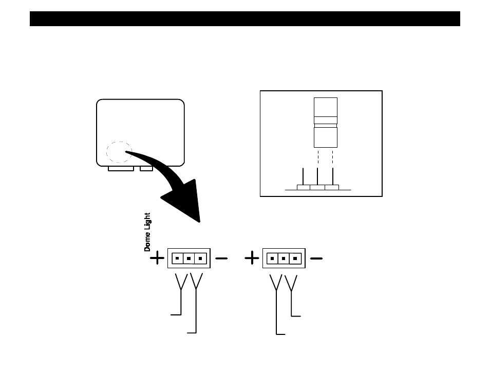
JUMPER PIN DIAGRAM
The jumper plugs inside the control module determine the unit's (+12V) or (-) Negative Parking & Dome Light
Relay outputs (White & Black/White wires). Use the jumper pins to change the Positive or Negative Polarity of
the outputs as required for your particular installation. (Default = Positive for Parking Light and Negative for
Dome Light) See diagram below.
JUMPER
PLUG
SIDE VIEW
JUMPER
PINS
(-) NEG. DOME LIGHT
CS-865RKE MODULE
+12V PARKING LIGHT
(DEFAULT)
TOP VIEW OF JUMPER PINS
(-) NEG. PARKING LIGHT
+12V DOME LIGHT
(DEFAULT)
Parking Light
JUMPER
See also other documents in the category Crimestopper Security Products Car alarm:
- EZ-95FM (32 pages)
- RS800 Series II (4 pages)
- CS-2008PC (19 pages)
- EZ-777 TW2 (16 pages)
- EZ-64TW1 (28 pages)
- CS-2011RS IV (30 pages)
- CS-2011RS IV (28 pages)
- SERIES II CS-2004DC II (27 pages)
- CS-2003DC SERIES II (18 pages)
- CS-2004TW1 (24 pages)
- CS-2004DC (20 pages)
- RS901 (13 pages)
- EZ-33DP (16 pages)
- CS-2016FM (21 pages)
- RS1905FM (32 pages)
- CS-2000DP-TW2 (24 pages)
- CS-2001 (12 pages)
- CS-2004DC (24 pages)
- CS-2000 (16 pages)
- CS-883 OEM (12 pages)
- CS-855RKE (12 pages)
- CS-2014TW2 (20 pages)
- RS-1704TW2 (20 pages)
- EZ-84FM (20 pages)
- RS900 (28 pages)
- Series IV Super Rage CS-2011RS (16 pages)
- EZ-10 (12 pages)
- EZ-30 (20 pages)
- CS-2000DPII TW2 (24 pages)
- CS-2205 (32 pages)
- EZ-30DP (29 pages)
- CS-2013FM (26 pages)
- CS-2100 (9 pages)
- CS-2001FC (20 pages)
- CS-2012DP-TW1 (32 pages)
- CS-2012DP-TW1 (32 pages)
- FS-20 (12 pages)
- CS-2011RS (16 pages)
- CS-882 (10 pages)
- CS-8050 (8 pages)
- TN-4011 (14 pages)
- GARGOYLE CS-2001FC (17 pages)
- EZ-45DP (14 pages)
- RS-1804FM (20 pages)