Gps external antenna – Trail Tech VOYAGER TOP MOUNT PROTECTOR 025-TM2 User Manual
Page 2
MADE IN AMERICA
Trail Tech and Voyager are trademarks of Trail Tech, Inc.
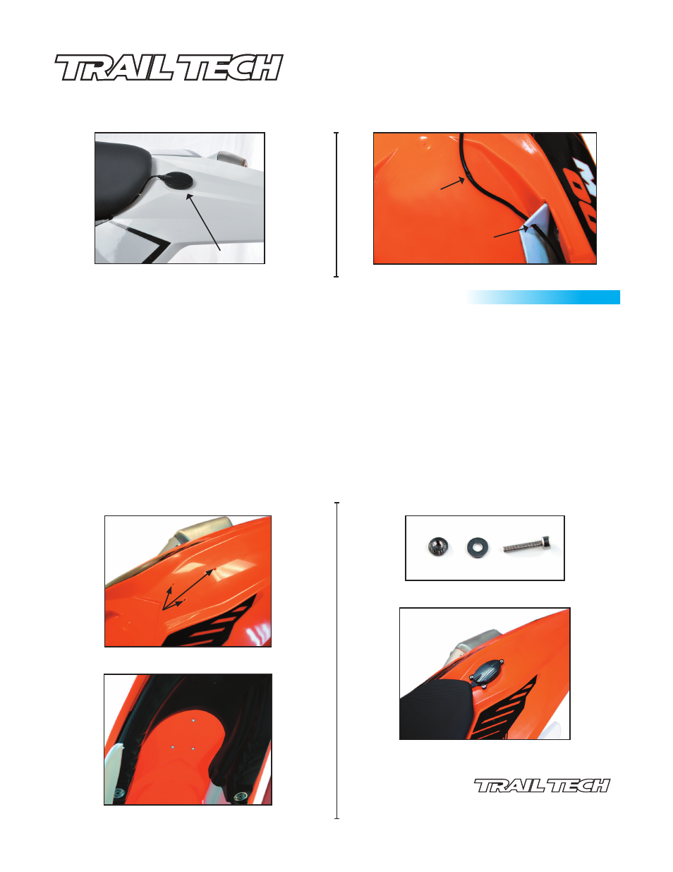
ANTENNA INSTALLATION OPTION 2 (BOLT ON INSTALLATION):
Step 1. Establish desired mounting location.
Step 2. Mark location of three mounting tabs on desired mounting location.
Step 3. Using a 3/16” drill bit, drill all three marked hole locations. (Fig. 6)
Step 4. Locate M3 x 20mm SCHS screw and M3 fender washer. (Fig. 7)
Step 5. Insert the self clinching nut, teeth up, into the under side of the mounting location. (Fig. 8)
Step 6. Place M3 fender washer on top of mounting location & insert M3x20SCHS into nut.
Step 7. Tighten the M3x20mm SCHS down until self clinching nut is firmly seated flush into the under side of mounting location. Repeat until all
three nuts are seated into mounting location.
Step 8. Discard M3x20mm SCHS & M3 fender washer. Note: These are for installation of self clinching nuts only & will not be used in final
installation.
Step 9. Locate three M3x12mm FHPS screws (9000-EAPK) and use for final mounting of antenna body by tightening them into self clinching nuts.
Note: Do not over tighten M3x12 FHPS. over tightening can strip the self clinching nuts out of the mounting location. Take care not to
push the self clinching nuts out of the mounting location. The self clinching nuts only hold force in the upward direction and can be
pushed out easily!
Fig. 5
Antenna Installed
010-ELV-118
Voyager External Antenna
Tech Support: 360-687-4530
GPS EXTERNAL ANTENNA
INSTALLATION GUIDE
Step 5.
Fig. 6
Drill Mounting Holes
Fig. 7
Fig. 8
Mounting Holes Drilled
M3x20mm SCHS & M3 Washer
Self Clinching Nuts Installed
Final Installation
Fig. 9
Watch for Bound or Pinched Antenna Wire
Antenna Wire
Pinched by Seat
Properly Routed to
Avoid Pinching
Fig. 5A