Taylor-Wharton EF-1000 User Manual
Page 9
BT-472 Rev. B
9
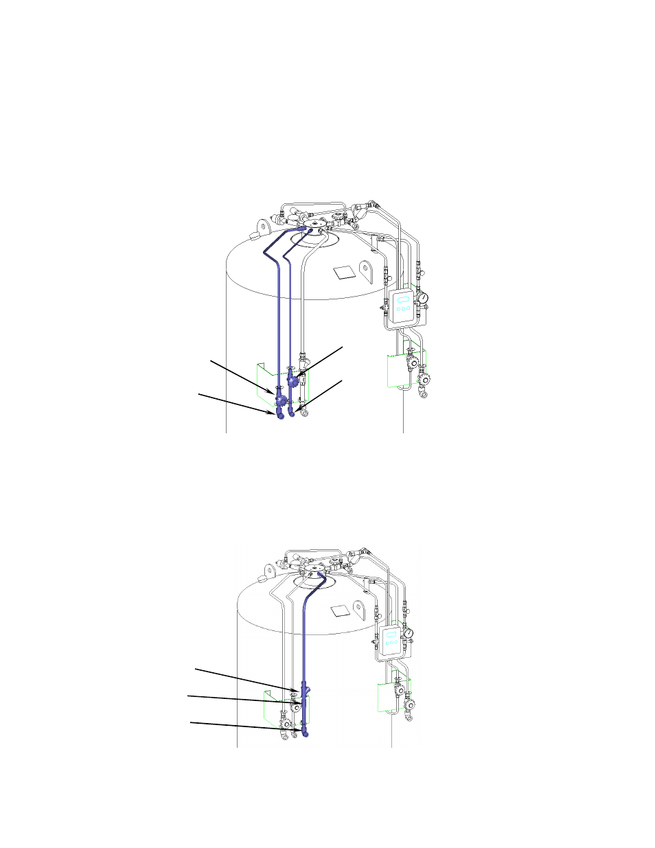
Fill and Vent Circuits
The liquid valve (V-1) communicates with the bottom of the vessel. A stainless steel tag labeled “LIQUID” identifies
the valve and the liquid connection (CN-1). Liquid is added or removed from the vessel through this connection and
valve.
The vent / trycock valve (V-2) is attached to a vertical tube in the upper portion of the vessel. The open end of the tube
is positioned at 90% liquid level based on the vessel volume. Opening the vent valve reduces pressure in the vessel
during filling. It also severs as a “full trycock”, venting liquid from the vessel when the liquid level exceeds 90%. A tag
labeled “VENT” is attached to this valve.
Figure 2: Fill and vent circuits highlighted in blue.
Express Fill Circuit
The Express Fill circuit may be used for filling from the Taylor-Wharton Express Cryogenic Delivery System or for top
filling by a cryogenic pump. Two check valves (CV-1 & CV-2) prevent product from escaping the vessel.
A fill stop valve (FSV-1) within the vessel prevents over filling. This device functions when filled by the Taylor-
Wharton Express Truck in automatic fill mode. The fill stop valve will not function when the vessel is filled by a typical
cryogenic pump.
Figure 3: Express Fill circuit highlighted in blue.
CV-1
CV-2 OR
V-1
CN-2
CN-1
V-2
CN-3
V-10