Wall mount for oscillating fan – Qmark LCHHD - Heavy Duty Oscillating Air Circulator User Manual
Page 3
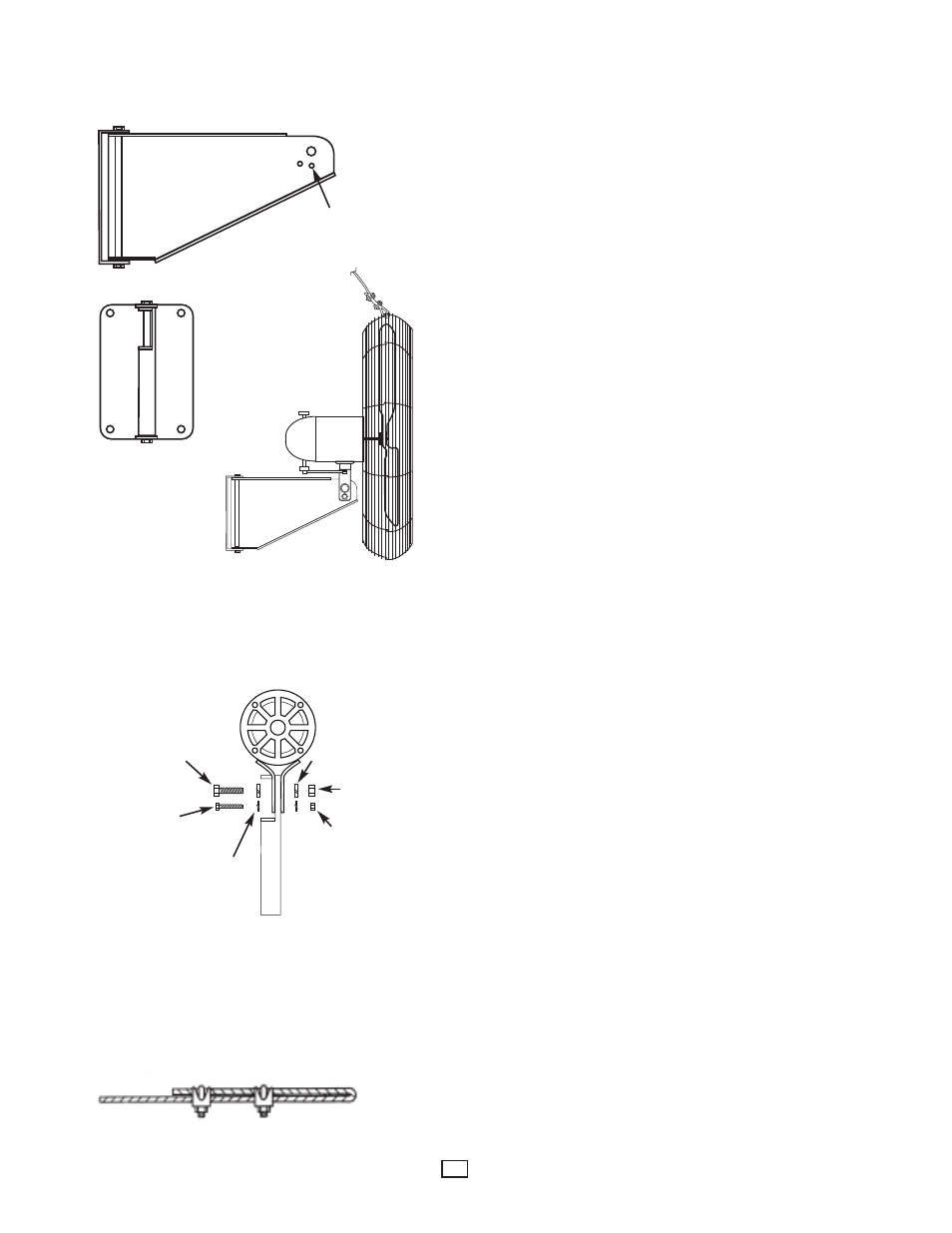
WALL MOUNT FOR OSCILLATING FAN
Figure 5
CAUTION: Do not install oscillating fans upside down as this may allow the fan
to fall or become permanently damaged. Mount only as shown in this manual
with the fan head on top of the bracket.
1. Securely mount the wall bracket directly to a cinder block wall or vertical I-beam.
Drill four 25/64” diameter holes in the proper locations on the mounting surface,
using the wall bracket as a template. 3/8-16 hex bolts are recommended for use
in mounting the bracket to the mounting surface. The bolts should be of suffi-
cient length for the particular surface to which the bracket is to be mounted. Also,
if mounting to a cinder block wall, large surface bearing washers are recom-
mended on the opposite side of the block to ensure the nut has sufficient surface
to be tightened. For installation on wood construction (minimum 2” x 4” stud),
secure bracket with heavy duty lag bolts or screws (not included). For concrete
or masonry installation use heavy duty expansion shields and lag screws (not
included). See Figure 5
NOTE: All installation should be done to meet local building codes.
2. Mount the motor assembly to the wall bracket using 1/2” x 1-1/2” hex bolt and
1/4” x 1-1/2” bolt, washers, lockwashers and hex nuts provided. See Figure 6
3. When mounting oscillating motor and fan assemblies, use only the 1/4” adjust-
ment hole directly below the 1/2” mounting hole on wall mount bracket. See
Figure 5.
NOTE: Use of the wrong hole on the wall bracket will cause the oscillating models
to tilt too much and will cause the oscillating mechanism to bind and cause pre-
mature failure.
4. DO NOT use an extension cord. For units which feature two part cordsets, con-
nect the male end of the motor cord to the female end of the cordset. Plug power
cord from fan into any 120 VAC 3 prong, grounded outlet.
SECONDARY SUPPORT CABLE INSTALLATION
For Overhead Wall Mounted Application
Loop secondary support cable around top of fan guard as indicated. Secure cable
making sure both front and back guards are inside loop but cable is not allowed to
touch fan blade (See Figure 5). Secure ends with two cable clamps, loop other end
of cable around any permanent sturdy structural member close to fan (rafter, I-
beam, joist, etc.) and secure ends with two cable clamps. Give enough slack such
that fan will be able to make its full sweep without the support cable restraining its
sweeping action.
IMPORTANT NOTICE: It is important to note the proper installation position of the
cable clamps as illustrated. To obtain maximum holding power, install U-bolt sec-
tion of clip on dead or short end of cable and saddle on long end of cable (See
Figure 7). Improper installation reduces the efficiency of the connection by as much
as 40 percent.
3
Oscillator motors use this
hole only for adjustment.
1/2-13 HHCS
Bolt
1/4-20 HHCS
Bolt
Lockwasher
Lockwasher
1/2-13 Hex Nut
1/4-20 Hex Nut
Figure 6
Figure 7