Important, Warning – Qmark Environmental Electric Heated User Manual
Page 7
7
TROUBLE SHOOTING CHART
Symptom
Possible Cause
Corrective Action
Fan inoperative
1. Blown fuse or open circuit breaker.
1. Replace fuse or reset circuit breaker
2. Electricity turned off.
2. Contact local power company.
3. Loose motor cord connection.
3. Re-check all connections.
4. Thermostat off/defective
4. Call for fan/Replace.
5. Defective fan relay/contactor.
5. Replace.
6. Defective fan relay/contactor.
6. Replace.
7. Defective capacitor (1 phase unit only)
7. Replace.
8. Defective motor.
8. Replace.
9. Wrong wiring.
9. Correct wiring.
Excessive noise
1. Wheel rubbing on housing.
1. Center wheel.
2. Motor base/blower loose.
2. Tighten mounting bolts.
3. Defective motor bearings.
3. Replace motor.
Insufficient air flow
1. Improper voltage.
1. Reconnect proper voltage or exchange unit
with proper voltage rating.
2. Outlet louvers closed.
2. Open louvers
3. Intakes obstructed.
3. Remove any obstruction.
4. Dirty blower wheels.
4. Clean.
5. Motor in reverse rotation.
5. Interchange red & black power leads.
Fan cuts out on thermal
1. Low voltage.
1. Check voltage/Use correct wire size.
overload (self-resets)
2. Obstruction to blower wheel.
2. Remove obstruction.
No heat
1. Fuse link open.
1. Replace w/ G5AM0400117C
2. Heater element broken.
2. Replace w/ proper Ga and watts.
3. Control transformer open
3. Check wiring /Reset control breaker
4. Auto reset functioned*
4. Wait to reset/check for insufficient airflow.
*Heat indicator light On (Main Panel)
BUT heat indicator light OFF (Cabinet)
4a. Auto reset functioned possibly due
4a. Remove cause of overheat/wait to reset.
to overheating.
4b. Air flow switch not closing its
4b. Check hose/switch/wiring & check for
normally open contact.
insufficient air flow.
5. Heat Indicator light OFF (Main Panel)
5. Adjust/check thermostat.
thermostat not calling for heat.
GENERAL SERVICING
1. To remove motor/blower assembly, repeat steps 4, 5, 6 and 7
in “Unpacking” section.
2. Place motor/blower assembly on workbench.
3. To replace blower wheel, remove the three slotted hex head
screws on outer blower ring assembly (See Figure 10,
Replacement Parts Illustration). The wheel is held onto shaft
by two hex head screws.
4. To remove motor:
a. Remove blower wheels. (See Step 3 above).
b. Remove blower scroll (six hex head screws).
c. Unscrew and remove motor mounts.
5. To remove heater assembly:
a. Remove blower wheels. (See Step 3 above).
b. Remove heater assembly (two screws). Disconnect two
yellow wires and blue, black and red wires from heating con-
tactor. Pass wires through bushing as you pull out the
heater assembly.
6. To replace heater assembly: Do the reverse of Step 5 above.
NOTE: To re-assemble, repeat steps 4, 5 and 6 in installation
section for single cabinet units.
7. Replace motor/blower assembly.
IMPORTANT
!
NOTE POSITION OF WHEELS TO PREVENT RUBBING WHEN
REPLACED.
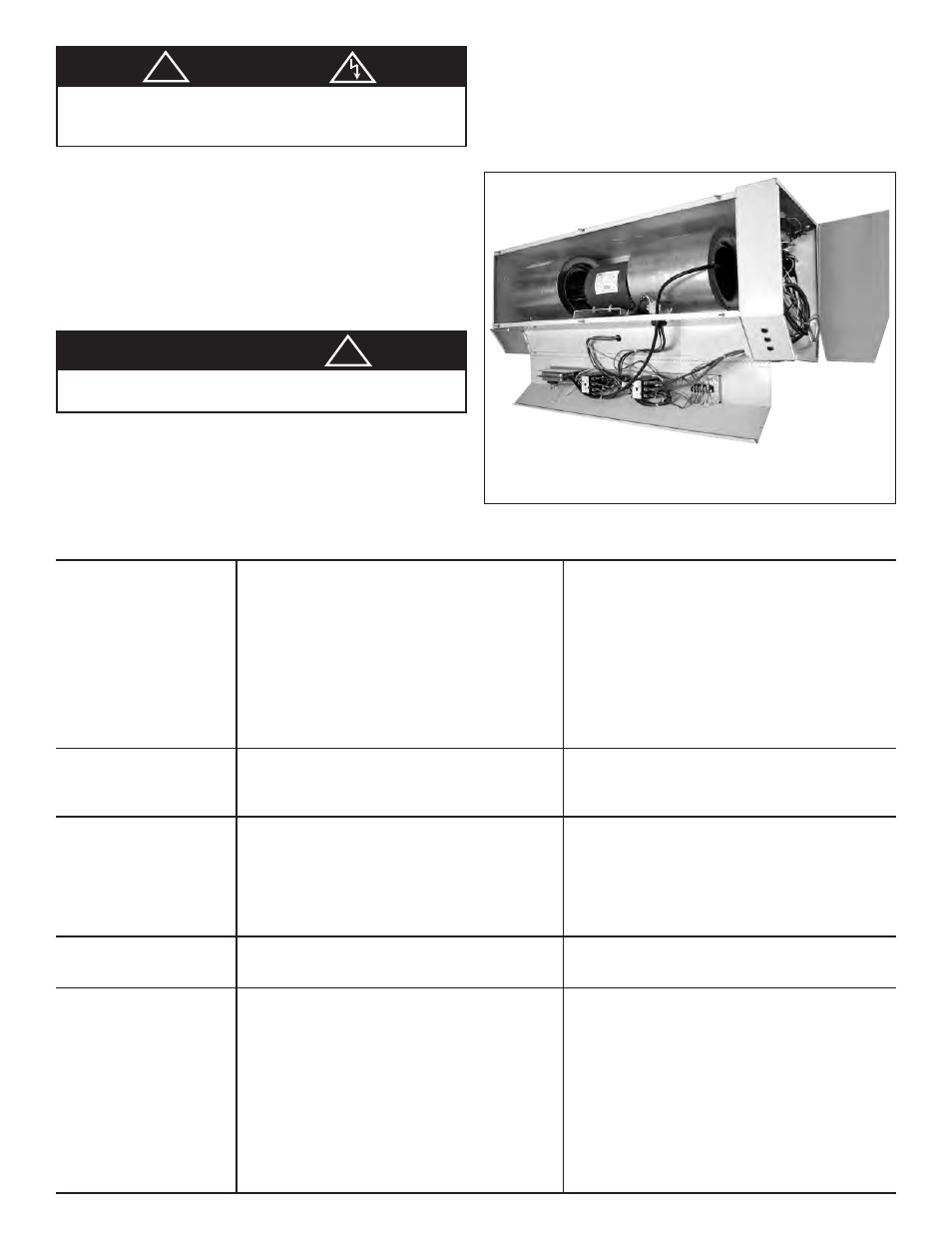
Figure 9 - Main control box cover & cabinet
compartment cover shown open and with air
intake grille removed.
!
WARNING
IF SERVICE IS REQUIRED, IT SHOULD BE DONE BY
QUALIFIED PERSONS ONLY.
ALWAYS DISCONNECT POWER SUPPLY BEFORE SERVICING