Warning, Caution – Qmark Environmental Electric Heated User Manual
Page 4
4
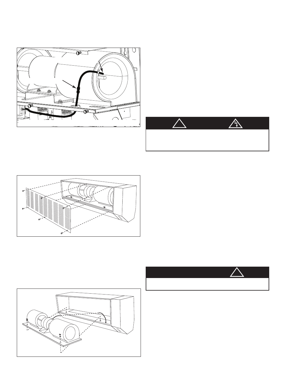
Important Note: The portion of the sensing tube that attaches to
the blower has an opening that must face the blower and be posi-
tioned near the center of the blower inlet. This should not be
removed or disturbed during the romoval and reinstallation of the
blower assembly into the cabinet. After reasembly, check to make
sure this sensing tube has not been damaged or dislodged. In the
control compartment, the sensing tube attaches to the “LOW” port
on the pressure differential switch.
When powering the unit for the first time, always check the wiring
for correctness and tightness, make sure the power supply
matches the nameplate rating of the unit, make sure the sensing
tubes of each PD switch are in the proper position and location
and all the cabinet compartment covers are closed. It is also rec-
ommended that the front grille covers should be in place. This will
make sure the pressure switch will sense enough vacuum and
turn on heater.
UNPACKING
For Single Cabinet Units: 36”, 42”, 48” and 60”
1. With packaged unit on the floor, carton arrows should point
upward.
2. Carefully remove staples from top of carton and fold back sides.
3. Carefully remove cabinet from carton by lifting out unit using fin-
ger holes in styrofoam side inset and place on work surface.
CAUTION: Do not attempt to lift this air curtain by its louver or
damage may result.
4. Unscrew six (6) knurled nuts and remove air intake grille. (See
Figure 3)
5. Carefully disconnect motor electric cord from socket and plug
assembly and remove two wing nuts on blower base. (See
Figure 4)
6. Carefully disconnect pressure switch hose quick connector at
blower by holding body of connector and pushing the release
ring towards the center of connector while pulling the hose to
disconnect.
7. To remove motor blower assembly, lift from rear of motor hous-
ing to prevent damage and misalignment to shaft and blower
wheels. Once the motor/blower assembly is removed, the heater
assembly will be accessed.
NOTE: After unpacking unit, inspect carefully for any damage that
may have occurred during transit. Check for loose, missing or dam-
aged parts. The hinged cabinet wiring compartment cover should
also be opened to inspect the components and wiring inside.
8. Make sure the open coil elements do not touch any metal part
and all the porcelains holding the elements are not broken and
are in their proper place.
For 2 Cabinet Units: 72”, 84” and 96” See Figure 5, Page 5
1. With packaged units on the floor, carton arrows should point
upward. Cartons are marked A & B.
2. Follow Steps 2 through 8 for Single Cabinet Units.
NOTE: Cabinet A (left), Cabinet B (right). Carton labeled
Cabinet B will contain the Main Control Box and all harness
wires and parts bag to interconnect the two cabinets.
For 3 Cabinet Units: 108”, 120”, 132” and 144”
See Figure 6, Page 6
1. With packaged units on the floor, carton arrows should point
upward. Cartons are marked A, B and C.
2. Follow Steps 2 through 8 for Single Cabinet Units.
NOTE: Cabinet A (left), Cabinet B (center), Cabinet C (right).
Carton labeled Cabinet C will contain the Main Control Box
and harness wires and parts bag to interconnect the three
cabinets. Cabinet B may also have harness wires to inter-
connect to Cabinet A.
INSTALLATION
For Single Cabinet Units:
NOTE: All installation should be done to meet local building codes.
1. Using template provided, determine mounting location.
2. Drill holes and attach mounting hardware (not included).
3. Mount cabinet on wall and securely tighten hardware.
4. Replace motor/blower assembly in cabinet. Pass pres-
sure switch hose through proper hole on blower base.
Reconnect motor electric cord plug assembly.
5. Attach pressure switch hose to quick connector at right
blower housing.
6. Secure two wing nuts on blower base.
Figure 3
Figure 4
!
WARNING
MAKE SURE NO COMBUSTIBLE MATERIAL NOR ANY
OTHER FOREIGN MATERIAL FALLS ON THIS HEATING
ELEMENT CAVITY WHILE IT IS EXPOSED WITH THE
MOTOR/ BLOWER ASSEMBLY OUT OF THE CABINET
CAUTION
!
THE HARDWARE AND THE SUPPORTING STRUCTURE MUST
BE CAPABLE OF SUPPORTING A MINIMUM 150 LB LOAD.
Figure 3: Sensing Tube Location
Quick connector
Sensing tube location