Unpacking, Installation, Electrical connections – Qmark Low-Profile User Manual
Page 2
Specifications
UNPACKING
1. With packaged unit on floor, carton arrows should point
upward.
2. Carefully remove staples from top of carton and fold back
sides.
3. Carefully remove cabinet by lifting out unit and place on work
surface.
4. Remove four (4) phillips screws securing mounting bracket
and remove unit mounting bracket.
INSTALLATION
1. Determine mounting location utilizing unit mounting bracket
and attach unit mounting bracket using appropriate mounting
hardware (not included).
IMPORTANT: The hardware and the supporting structure must
be capable of supporting a minimum 150 lb. load.
NOTE: All installation should be done to meet local building
codes.
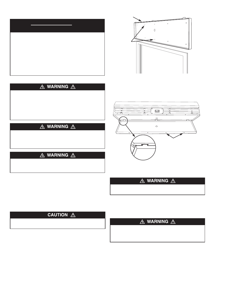
2. Mount air curtain cabinet assembly by simply “hanging” unit
onto unit mounting bracket by aligning vertical tabs with air
curtain cabinet assembly slots (Figure 2). Secure air curtain
to mounting bracket by four (4) phillips screws.
ELECTRICAL CONNECTIONS
Cord Connected
1. Connect power per nameplate to correct power supply.
2. Install all wiring, protection, and grounding in accordance
with the National Electrical Code (NEC) and all requirements.
3. Unit is ready for operation.
4. Confirm unit is operating within all electrical and performance
specifications.
NOTE: Air curtain has high/low selector switch that is factory
wired
THIS FAN HAS AN INTERNAL SELF-RESETTING THERMAL
OVERLOAD PROTECTOR. ALWAYS DISCONNECT FROM
POWER SUPPLY BEFORE SERVICING.
ALL AIR CURTAINS SHOULD BE INSTALLED BY QUALIFIED
PERSONNEL.
DO NOT ATTEMPT TO LIFT THIS AIR CURTAIN BY ITS
LOUVER OR DAMAGE MAY RESULT.
TO REDUCE THE RISK OF FIRE OR ELECTRIC SHOCK, DO
NOT USE THIS AIR CURTAIN WITH ANY SOLID STATE
SPEED CONTROL DEVICES.
THIS PRODUCT MUST NOT BE USED IN POTENTIALLY
DANGEROUS AREAS SUCH AS HAZARDOUS LOCATIONS,
FLAMMABLE, EXPLOSIVE, CHEMICAL-LADEN, OR WET
ATMOSPHERES ARE PRESENT.
DO NOT DEPEND UPON A THERMOSTAT OR OTHER
SWITCH AS THE SOLE MEANS OF DISCONNECTING
POWER WHEN INSTALLING OR SERVICING THE UNIT.
ALWAYS DISCONNECT AND LOCK OUT POWER AT THE
MAIN CIRCUIT BREAKER AS DESCRIBED ABOVE.
FAILURE TO DO SO COULD RESULT IN FATAL ELECTRIC
SHOCK.
2
AIR DELIVERY
Dim.
Avg. FPM
CFM
Total
Max
Model No.
“A”
at Nozzle
at Nozzle
HP
Amps
Volts
LP36001115
37.0
1800/1350
1295/971
1/15
1.3A
120
LP42001110
42.0
1800/1350
1470/1103
1/10
1.6A
120
LP48001108
48.0
1800/1350
1681/1260
1/8
2.1A
120
LP60001108
60.0
1800/1350
2102/1576
1/8
2.1A
120
LP36001208
37.0
1800/1350
1295/971
1/8
0.7A
240
LP42001208
42.0
1800/1350
1470/1103
1/8
0.7A
240
LP48001206
48.0
1800/1350
1681/1260
1/6
1.0A
240
LP60001206
60.0
1800/1350
2102/1576
1/6
1.0A
240
Figure 1
Figure 2
Fit tab of mounting bracket into
slot on back of unit as shown
Screw holes (4)
Mounting bracket
Mounting holes
(10 total)