Dell POWEREDGE M1000E User Manual
Page 23
Rev 1.0
24
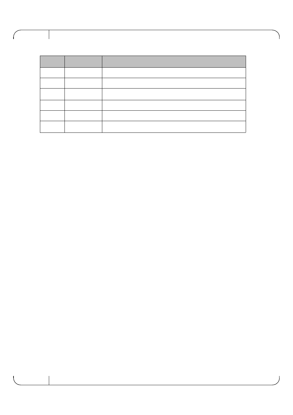
15
VccR
Receiver Power Supply
16
VccT
Transmitter Power Supply
17
VeeT
Transmitter Ground (Common with Receiver Ground)
a
18
TD+
Transmitter Non-Inverted DATA in. AC Coupled.
19
TD-
Transmitter Inverted DATA in. AC Coupled.
20
VeeT
Transmitter Ground (Common with Receiver Ground)
a
a. Circuit ground is internally isolated from chassis ground.
b. T
FAULT
is an open collector/drain output, which should be pulled up with a 4.7k – 10k
Ohms resistor on the host board if intended for use. Pull up voltage should be between 2.0V
to Vcc + 0.3V. A high output indicates a transmitter fault caused by either the TX bias cur-
rent or the TX output power exceeding the preset alarm thresholds. A low output indicates
normal operation. In the low state, the output is pulled to <0.8V.
c. Laser output disabled on TDIS >2.0V or open, enabled on TDIS <0.8V
d. Should be pulled up with 4.7kΩ – 10kΩ on host board to a voltage between 2.0V and 3.6V.
MOD_ABS pulls line low to indicate module is plugged in.
e. LOS is open collector output. Should be pulled up with 4.7kΩ – 10kΩ on host board to a
voltage between 2.0V and 3.6V. Logic 0 indicates normal operation; logic 1 indicates loss of
signal.
Table 9 - SFP+ Pinout
Pin
Symbol Name
Description