T network status (see, Network switch module features, System management module features – Dell PowerEdge 1655MC User Manual
Page 7
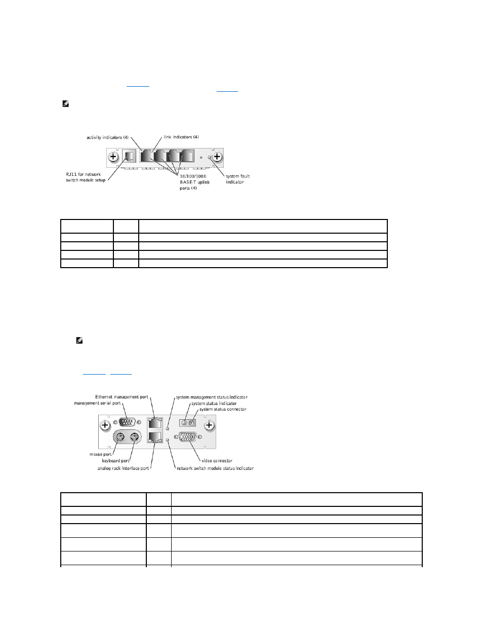
Network Switch Module Features
Each system can accommodate up to two network switch modules. The network switch modules provide information about network activity and link status and
a system fault indicator (see
). The switch also provides an external RJ11 connection to a serial null modem cable used for switch setup and
configuration. The RJ11 is not used during normal system operation.
provides details about the operation of the indicators.
Figure 1-6. Network Switch Module Indicators and Features
Table 1-4. Network Switch Module Indicator Codes
System Management Module Features
The system management module provides:
l
Keyboard/mouse/video access to each server module
l
Serial and Ethernet management ports
l
An analog rack interface port to attach to an optional external KVM over IP switch
l
Status indicators for the system management module and for the link to the system's onboard network switch module.
In addition, a system status connector allows you to attach the system status cable so that you can monitor system status after the system is mounted in a
rack (see
provides information about the status indicators.
Figure 1-7. System Management Module Features
Table 1-5. System Management Module Indicators
NOTE:
Do not connect the configuration port to a data or telephone network.
Indicator Type
Activity
Indicator
Indicator Code
Network indicator
Green
The port is connected to a valid link partner on the network.
Blinking
Network data is being sent or received.
System fault indicator Green
Indicates normal system operation.
Amber
Indicates a system power fault. See your system Installation and Troubleshooting Guide for more information.
NOTE:
Connect the analog rack interface port only to an external KVM over IP switch provided by Dell.
Indicator Type
Activity
Indicator
Indicator Code
System status indicator
Blue
System is operating normally.
Amber
A system fault is present. See your system Installation and Troubleshooting Guide for more information.
System management status
indicator
Green
System management module is operating normally.
Amber
Indicates a system management module fault. See your system Installation and Troubleshooting Guide for
more information.
Network switch module status
indicator
Green
Indicates that the system management module and the onboard network switch module are communicating.