Back-panel features, Power-supply indicator – Dell PowerEdge 1655MC User Manual
Page 6
2.
Place the drive on the shelf and attach the drive to the server module that you want to configure.
3.
Remove the drive and the drive shelf. Do not leave the drive attached during normal system operation.
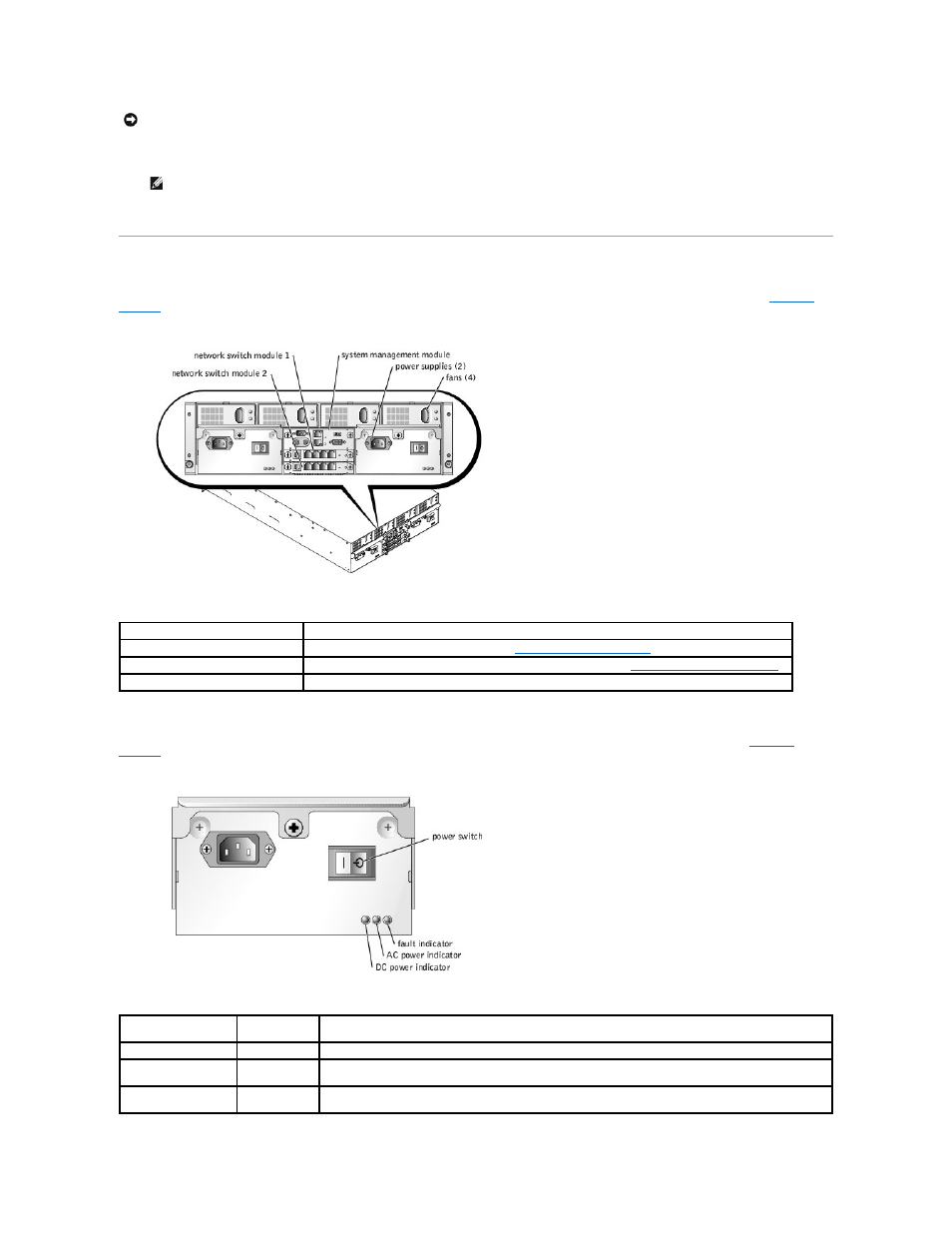
Back-Panel Features
The back of the system provides access to the network switch modules (2), the system management module, the fans, and power supplies (see
).
provides information about the back-panel features.
Figure 1-4. Back-Panel Features
Table 1-2. Back-Panel Features
Power-Supply Indicator
Each hot-pluggable power supply has indicators that can provide information about power status, fault, and the presence of AC power (see
).
lists the power-supply indicator codes.
Figure 1-5. Power-Supply Indicators
Table 1-3. Power-Supply Indicator Codes
NOTICE:
The USB diskette or USB CD drive must be placed on the drive shelf during operation. The drive must be horizontal and level to operate
properly.
NOTE:
If the drive must be designated as the boot drive, reset the power on the server module.
Component
Description
Power supply indicators
Provide information about power status (see "
").
Network switch module indicators
Provide information about the 10/100/100 BASE-T network status (see "
Network Switch Module Features
System management module indicators Provide information about system status, system management status, and port status.
Indicator
Activity
Indicator
Indicator Code
DC power indicator
Green
Indicates that the power supply is operational.
AC power present
indicator
Green
Indicates that AC power is present at the power supply and that the system is connected to an AC power
source.
Fault indicator
Amber
Indicates that the power supply is in a fault condition. See your system Installation and Troubleshooting Guide for
more information.