System board components, System board jumpers – Dell OptiPlex GX100 User Manual
Page 50
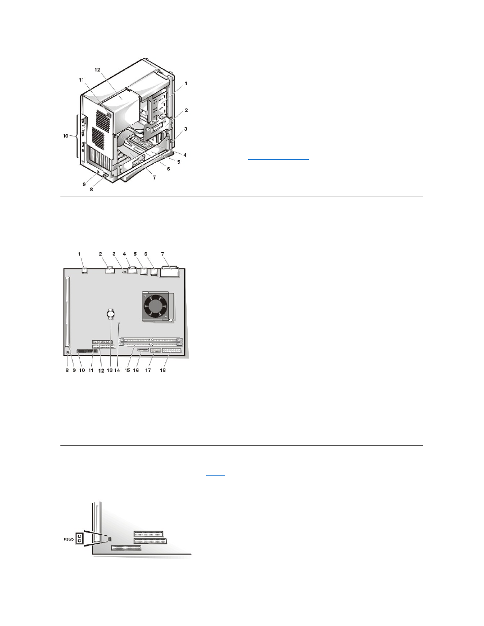
System Board Components
Figure 7 shows the system board and the location of all its sockets and connectors.
Figure 7. System Board Components
System Board Jumpers
Figure 8 shows the layout of jumpers on the system board.
lists the system board jumpers and their settings.
Figure 8. System Board Jumpers
1 External drive bay
2 Internal drive cage
3 Chassis intrusion switch
4 Hard-disk drive interface cable
5 Expansion-card cage
6 System board
7
Riser board
8 Padlock ring
9 Security cable slot
10
I/O ports and connectors
11 AC power receptacle
12 Power supply
1 NIC connector
2 Video connector
3 Fan connector
4 Serial port 2 connector
5 USB connectors (2)
6 Keyboard (lower) and mouse (upper) connectors
7 Parallel port (upper) and serial port 1 (lower) connectors
8 System board jumpers
9 Riser board connector
10 IDE1 connector
11 IDE2 connector
12 Diskette/tape-drive connector
13 Battery
14 Auxiliary power indicator
15 DIMM connectors (2)
16 Control panel connector
17 3.3-V power connector
18 DC power connector