Carrier 30XA080-500 User Manual
Page 2
2
7. Wire the coils of pump contactors (PMP1-A1, A2 and
PMP2-A1, A2) to TB5-11 and 13 (pump 1) and TB5-13
and 15 (pump 2) as shown in Fig. 2 with field-supplied
18 AWG wires and wire terminals.
NOTE: If only one pump is available in the system (no
backup pump), the wiring for PMP2 is not required.
8. Locate the main base board in the main control panel.
Refer to Fig. 3. Near CH18 (J5C) of the board, there are
violet and pink wires tied up outside the wire duct termi-
nated with wire nuts. These wires are for pump auxiliary
contact wiring. Remove the wire nuts and connect the two
wires to the pump auxiliary contacts per Fig. 3 with field-
supplied wiring. Some units may not be supplied with the
J5C connector and the violet and pink wires. A 2-pin con-
nector (Item 8) is supplied if these parts are not present.
Wire the pump contactor auxiliary contacts to the 2-pin
connector. Insert the 2-pin connector into MBB-J5C.
NOTE: If only one pump is available in the system (no
backup pump), the wiring for PMP-2 is not required.
Configuration (All Sizes) —
The control must be
configured for pump control operation. Use the Navigator™ or
the Touch Pilot™ display to configure the system. To configure
the system with the Navigator display, follow the steps below.
1. Set the Enable/Off/Remote switch to OFF position.
2. Press ESCAPE until the Select a Menu Item is displayed
on the screen. Use the arrow key to select the Configura-
tion mode LED.
3. Press ENTER, then use the arrow key to select the
sub-mode ‘OPTN’, press ENTER.
4. Press the down arrow key until ‘PUMP’ is displayed.
5. Press the ENTER key twice. The word ‘PASS’ and
‘WORD’ will flash.
6. Press 0 1 1 1 then ENTER key so that ‘0’ flashes.
7. Use arrow keys to change value to one of the descriptions
in Table 2.
Table 2 — Pump Control Configuration Options
*Used with dual pumps.
8. The unit is now configured for pump control.
To configure the system with the Touch Pilot display, follow
the steps below.
1. Ensure the unit is in Local Off operating mode by looking
at the left upper corner of the group display. If the unit is
not in Local Off mode, push the Start/Stop (0/1) button to
switch it to the Local Off mode.
2. Push the Main Menu button on the bottom line of display,
and then follow the path Config
→
USER to the USER
table.
3. Scroll down the screen by pushing scroll down button or
page down button until Cooler Pumps Sequence is
displayed. Push Cooler Pumps Sequence and the Point
Data menu will display.
4. Push the Modify button within the Point Data menu. If
the login menu displays, log in with the password of
3333, then press the OK button to confirm the input. The
value of CCN variable cpumpseq will display. Enter 1, 2,
3, or 4 per Table 2 and press the OK button to confirm the
input.
5. Push the Home button. A save confirmation menu will
display. Press the OK button to confirm.
6. The unit is now configured for pump control.
Test Pump Control Output —
Use the Navigator or
Touch Pilot display, the instructions given in the Controls,
Start-Up, Operation Service and Troubleshooting manual and
the Service Test mode to verify proper operation of pump
output. Be sure to turn off the fuse or circuit breaker for the
pump(s) and verify that the pump contactor(s) is being
energized during the test. For the Navigator display, illuminate
the Service Test LED, enter the TEST mode, enable the test
request, (‘T.REQ’) and test outputs (‘PMP.1’, ‘PMP.2’). For the
Touch Pilot display, from the main menu, follow the
Status
→
QCK_TST1, enable the Quick Test, and test outputs
(‘Water Exchanger Pump 1’, ‘Water Exchanger Pump 2’).
Once the outputs have been tested, the installation is complete.
Return the Enable/Off/Remote contact switch to the desired
position. Restore power to the pumps.
CONFIGURATION
DESCRIPTION
0
No Pump Control
1
1 Pump Only
2
2 Pumps Auto*
3
PMP 1 Manual
4
Pump2 Manual*
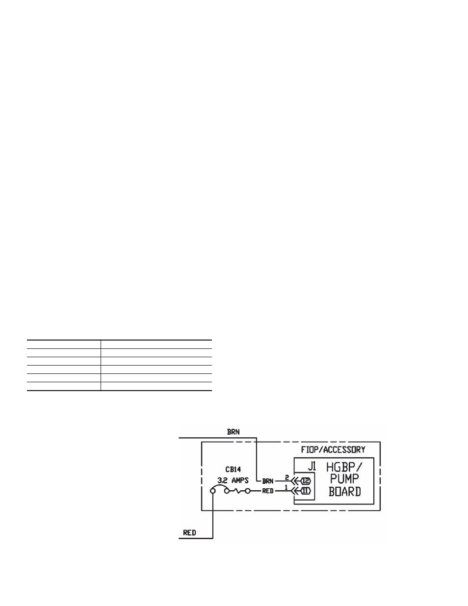
TB10-X2 (080-120 SIZES, 460/575 V)
TB11-X2 (ALL OTHER UNITS)
TB10-X1 (080-120 SIZES, 460/575 V)
TB11-X1 (ALL OTHER UNITS)
Fig. 1 — Pump Board 24 V Power Wiring
a30-4444