Cabletron Systems FOT-F3 User Manual
Page 24
CHAPTER 3: INSTALLATION
3-4
FOT-F3 USER’S MANUAL
2.
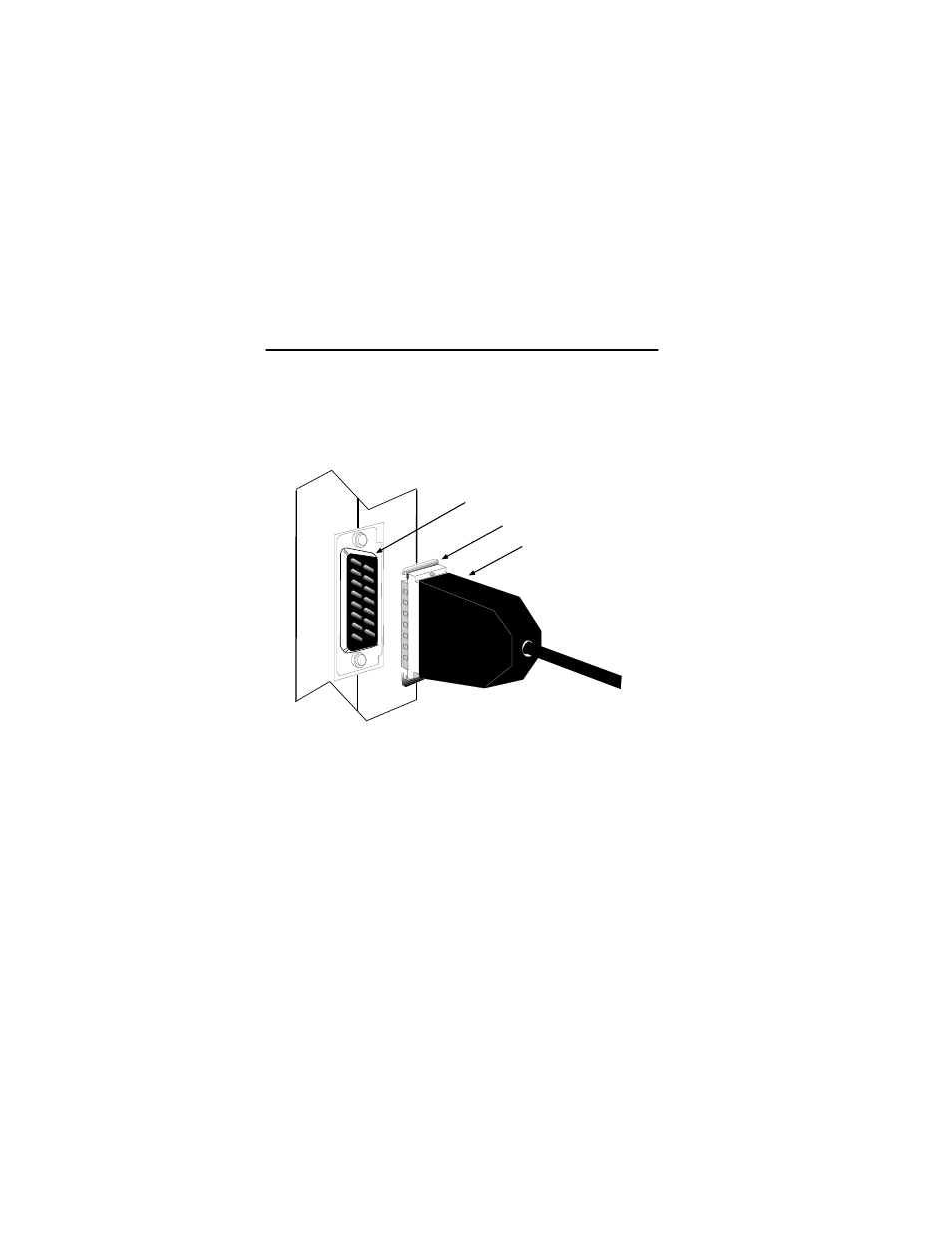
Attach the female connector on the AUI cable to the AUI
port on the FOT-F3. If the power is on for the Ethernet
device, the PWR LED should be lit, indicating the
transceiver is receiving power from the device. Also, if the
SQE test is enabled, the SQE LED should be lit.
Figure 3-2 AUI Connection
If the PWR LED is not lit, perform the following steps:
a.
Verify that the power is turned on for the device
attached to the FOT-F3.
b.
Disconnect the AUI cable from the FOT-F3.
SLIDE LATCH
AUI CONNECTOR
0461-07
Slide Latch
AUI Port
AUI Connector
See also other documents in the category Cabletron Systems Hardware:
- FOT-F3 (41 pages)
- BRIM-F6 (41 pages)
- WPIM-RT1 (50 pages)
- BRIM-WT1 (32 pages)
- 36 (33 pages)
- 9T101-04 (28 pages)
- FDDI Repeater (29 pages)
- SWPIM-BRI (34 pages)
- 9C114 (26 pages)
- SMARTSWITCH ROUTER 9032578-05 (398 pages)
- HSIM-W6 (258 pages)
- NB25 E (30 pages)
- HSIM-G01 (36 pages)
- HSIM-FE6 (42 pages)
- Expansion module 9E429-36 (18 pages)
- EMM-E6 Ethernet (205 pages)
- Environmental Module TM 9C300-1 (50 pages)
- CSMIM-T1 (198 pages)
- NBR-620 (73 pages)
- E2100 (42 pages)
- KBU64 Rackmount (26 pages)
- AirConnect 3Com (93 pages)
- 802.1Q (92 pages)
- W85 (60 pages)
- ELS10-26 (170 pages)
- Expansion module 9E106-06 (40 pages)
- 6H259-17 (58 pages)
- Expansion module 9F120-08 (12 pages)
- EMC39-12 (33 pages)
- 6A000/ZX-250 (268 pages)
- Expansion module DELHE-UA (50 pages)
- Expansion module 9T122-08 (36 pages)
- DMS-100 (196 pages)
- BRIM E100 BRIM-E100 (42 pages)
- Cabletron CyberSWITCH CSX400 (275 pages)
- Cabletron SmartSwitch Router 250 (34 pages)
- Network Router (100 pages)
- 9W111-08 (28 pages)
- CSX400 (101 pages)
- Cabletron SmartSwitch Router 510 (106 pages)
- SEHI-32/34 (90 pages)
- SmartSwitch (338 pages)
- 9T106-01 (28 pages)
- Switch 9H531-17 (38 pages)