Cleveland, Utilities – Cleveland Range CSTK-610 User Manual
Page 7
Cleveland
™
Project ________________________________
Item __________________________________
Quantity _______________________________
FCSI Section ____________________________
Approval _______________________________
Date __________________________________
1333 East 179 St.,
Cleveland, Ohio, U.S.A. 44110
Tel: 1-216-481-4900
Fax: 1-216-481-3782
Web Site: www.ClevelandRange.com
Email: [email protected]
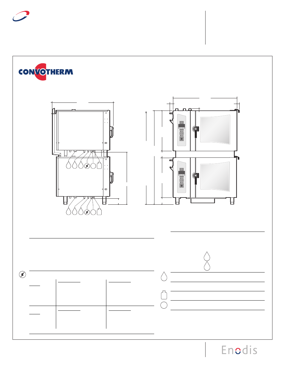
COMBI OVEN-STEAMER
Stacking Kits for Electric Table Type Models
(OEB 6.20 on OEB 6.20 or OES 6.20 on OES 6.20)
by
by
Cleveland
Cleveland
™
Model #
Description
CSTK-620
for mounting two 6.20 models
CSTK-620CA
for mounting two 6.20 models (with casters)
7
1
.2
0
"
47.92"
2.52"
1.58"
1.82"
3
0
.1
2
"
5.00
"
3
0
.1
2
"
6.00"
7
8
.0
0
”
(M
IN
.H
O
O
D
R
E
Q
U
IR
E
M
E
N
T
)
RC
CS
W1
W2
D
RC
CS
W1
W2
D
4.38"
39.50"
46.34"
NOTE: Overall height of unit does not change for units with casters.
UNIT A
UNIT A
UNIT B
UNIT B
LEFT SIDE VIEW
FRONT VIEW
6
6.20
on 6.20
ELEC
6
20
37.83"
LEFT SIDE VIEW
36.70"
1.58"
1.82"
2.52"
RC
CS
W1
W2
D
38.08"
2
8
.4
3
5.00"
6
7
.8
5
"
2
8
.4
3
7
8
.0
0
”
(M
IN
.H
O
O
D
R
E
Q
U
IR
E
M
E
N
T
)
UNIT A
UNIT B
UNIT A
UNIT B
R
6.10
on 6.10
ELEC
6
UTILITIES
(Utility connection shown below are listed per unit)
Required Clearances:
Rear - 2", Left Side - 4", Right Side - 2 1/2"
• Allow for sufficient distance if a "high heat source" (i.e. Broiler) is located next to
the unit.
• Allow for sufficient clearance on left side for service access (contact the factory
service department for recommendations).
• Installation must comply with all local fire and health codes.
Electrical Requirements:
Do not connect to a G.F.I. outlet.
BOILER
UNIT A - OEB-6.20
UNIT B - OEB-6.20
MODELS
208/3/60 240/3/60
440/3/60 480/3/60
208/3/60 240/3/60 440/3/60 480/3/60
Total Connected Load:
16.4 KW 21.6 KW
18.5 KW 22 KW
16.4 KW 21.6 KW
18.5 KW 22 KW
Hot Air:
14.7 KW
19.6 KW
16.5 KW 19.6 KW
14.7 KW 19.6 KW
16.5 KW 19.6 KW
Steam Generator:
12.8 KW
17.1 KW
14.3 KW 17.1 KW
12.8 KW 17.1 KW
14.3 KW 17.1 KW
Amps per Phase:
45.5
51.8
24.2
26.4
45.5
51.8
24.2
26.4
BOILERLESS
UNIT A - OES-6.20
UNIT B - OES-6.20
MODELS
208/3/60 240/3/60
440/3/60 480/3/60
208/3/60 240/3/60 440/3/60 480/3/60
Total Connected Load:
16.4 KW 21.6 KW
18.5 KW 22 KW
16.4 KW 21.6 KW
18.5 KW 22 KW
Hot Air:
14.7 KW
19.6 KW
16.5 KW 19.6 KW
14.7 KW 19.6 KW
16.5 KW 19.6 KW
Amps per Phase:
45.5
51.8
24.2
26.4
45.5
51.8
24.2
26.4
W1
W2
D
RC
S
CS
AV
G
E1
SECT.
IIB
PAGE
5G
0707
Water Connections:
Cold Water (drinking water quality)
Flow Pressure:
30 - 60 PSI
Water Inlets:
3/4" GHT-F (Female Garden Hose
Connection)
Treated Water for Steam Generator
Untreated Water for Condenser
Drain Connection:
2" Tube
Venting:
Exhaust Hood required
*Connection for Cleaning Solution
*Connection for Rinse Cycle
*Available as an option
Note: For additional connection details,
see spec sheet for each individual
combi model to be stacked.
W1
W2
D
RC
S
CS
AV
G
W1
W2
D
RC
S
CS
AV
G
W1
W2
D
RC
S
CS
AV
G
E1
E2
W1
W2
D
RC
S
CS
AV
W1
W2
D
RC
S
CS
AV
G