Installing the main unit, General cautions, Cautions on installation – Clarion VRX610 User Manual
Page 23
VRX610
45
44
VRX610
■
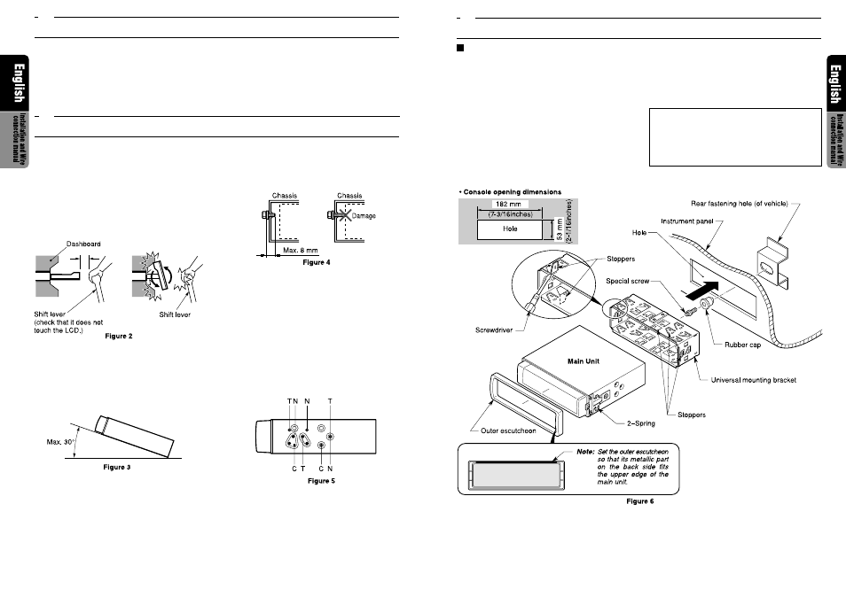
Universal Mount
1.
Place the universal mounting bracket into the
instrument panel, use a screwdriver to bend
each stopper of the universal mounting
bracket inward, then secure the stopper as
shown in Figure 6.
2.
Wire as shown in Section 8.
3.
Insert the main unit into the universal mount-
ing bracket until it locks.
4.
Mount the outer escutcheon so that all the
hooks are locked.
Notes:
1) Some car models require special mounting kits
for proper installation. Consult your Clarion
dealer for details.
2) Fasten the front stopper securely to prevent
the main unit from coming loose.
5.
INSTALLING THE MAIN UNIT
(2.09inches)
1.
Do not open the case. There are no user
serviceable parts inside. If you drop anything
into the unit during installation, consult your
dealer or an authorized CLARION service
centre.
2.
Use a soft, dry cloth to clean the case. Never
use a rough cloth, thinner, benzine, or alco-
hol, etc. For tough dirt, apply a little cold or
warm water to a soft cloth and wipe off the
dirt gently.
1.
Prepare all articles necessary for installing
the main unit before starting.
2.
This model is used with the LCD panel slid
forwards (shell loading system). On some
types of cars, the LCD panel may touch the
dashboard or shift lever, in which case it can-
not be installed. Check that the set will not
hamper operation of the shift lever before
choosing the place of installation.(Figure 2)
3.
Install the unit within 30
°
of the horizontal
plane. (Figure 3)
4.
If you have to do any work on the car body,
such as drilling holes, consult your car dealer
beforehand.
5.
Use the enclosed screws for installation.
Using other screws can cause damage. (Fig-
ure 4)
6.
The source unit has mounting screw holes
for NISSAN (N marks) and TOYOTA (T
marks) vehicles, and for Clarion installation
kit (C marks).
When you use a mounting kit sold separately,
affix the screws to the
●
marks above ac-
cording to the type of the vehicle. (Figure 5)
3.
GENERAL CAUTIONS
4.
CAUTIONS ON INSTALLATION