Installing the lift arm, Installing base end of lift arm, Installing display end of lift arm – Chief Manufacturing KSA-1004 User Manual
Page 5
Installation Instructions
FSA/KSA-1004
5
Installing the Lift Arm
To install the lift arm, perform the following procedures:
Installing base end of lift arm
1. Locate the tension adjustment bolt on the lift arm
(see Figure 3). Install the pivot pin (40) and a washer
(20) onto the base of the mount.
2. Assemble a button head cap screw (50), one
stainless steel washer (70), washer (30), and a
second stainless steel washer (70) onto button head
cap screw (50) as shown in Figure 3.
3. Insert the screw assembly (step 2) into the pivot hole
on the lift arm (10) and the base end of the mount.
4. Thread the lock nut (60) to the screw assembly (step
2) at the bottom of the mount.
CAUTION: Over-tightening a tension screw (50) will
cause excessive wear and may distort
adjustment components.
5. Using the 3/16” hex key (provided), tighten the
button head cap screw (50) into the nut (60) several
turns, leaving flexibility in the hinged joint. Do not
over-tighten the cap screw (50).
Installing display end of lift arm
1. Install the original pivot pin (see Figure 3) that was
retained when the display was removed and a
washer (20) onto the base of the mount.
2. Assemble a button head cap screw (50), one
stainless steel washer (70), washer (30), and a
second stainless steel washer (70) onto button head
cap screw (50) as shown in Figure 3.
3. Insert the screw assembly (step 2) into the pivot hole
on the lift arm (10) and the display end of the mount.
4. Thread the lock nut (80) to the screw assembly (step
2) at the bottom of the mount.
CAUTION: Over-tightening a tension screw (50) will
cause excessive wear and may distort
adjustment components.
5. Using the 3/16” hex key (provided), tighten the
button head cap screw (50) into the nut (80) several
turns, leaving flexibility in the hinged joint. Do not
over-tighten the cap screw (50).
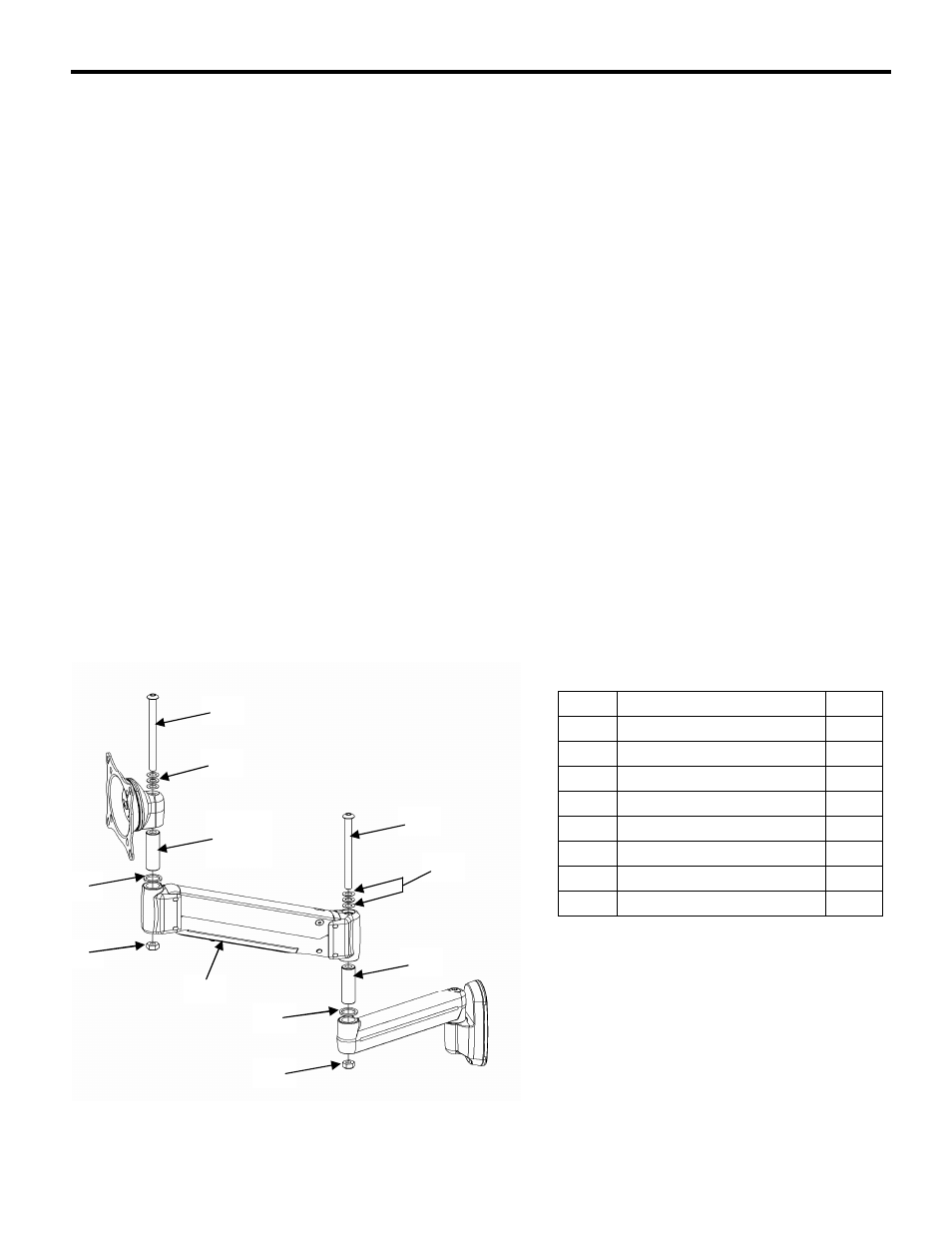
Figure 3. Installing Lift Arm
Lift Arm Parts
ITEM
PART NAME
QTY
10
LIFT ARM
1
20
LARGE WASHER
,
NYLON
2
30
SMALL W ASHER
,
NYLON
2
40
PIVOT PIN
,
SPF
1
50
CAP SCREW
,
BUTTON HEAD
2
60
LOCK NUT
,
NYLOCK
1
70
SPACER
,
STAINLESS STEEL
4
80
LARGE LOCK NUT
,
NYLOCK
1
80
10
70
50
40
30
50
Original
Pivot
Pin
60
20
20