Crestron qm-da quickmedia™ distribution amplifier – Crestron electronic Manual QM-DA User Manual
Page 9
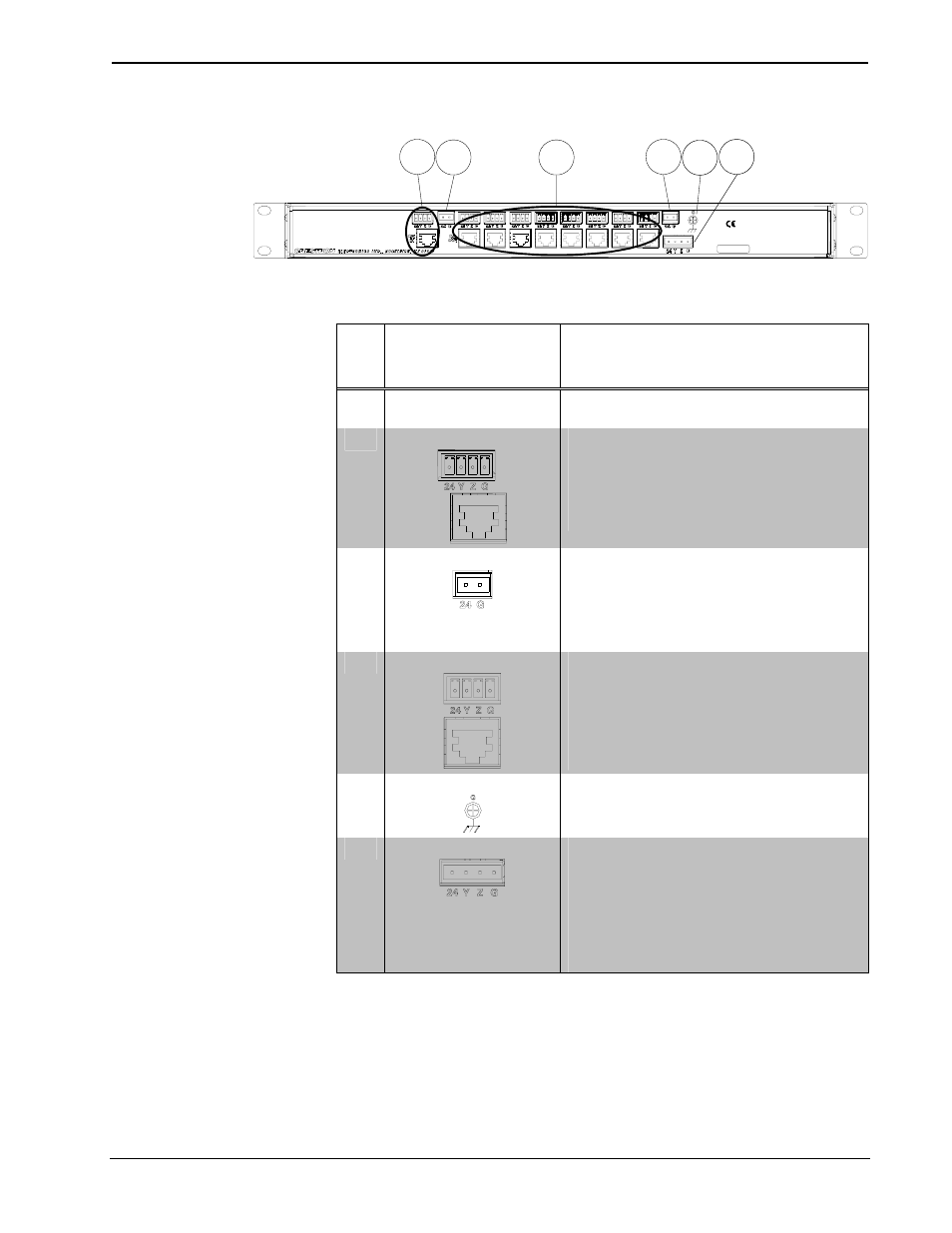
Crestron QM-DA
QuickMedia™ Distribution Amplifier
QM-DA (Rear View – QM-DA-8 Shown)
2
3
4
6
3
5
Connectors, Controls & Indicators
#
CONNECTORS
1
,
CONTROLS &
INDICATORS
DESCRIPTION
1 PWR
LED Indicates 24 Volts DC power supplied from
Cresnet control network.
2
QM IN
2, 3
(1) 8-wire RJ-45 female and (1) 4-pin 3.5 mm
detachable terminal block comprising (1)
QuickMedia input port with Cresnet;
Connects to Cresnet and QM output port of
another QuickMedia device via CresCAT-QM
cable.
4
3
24 G
(1, 2 or 4)
5
2-pin 5 mm detachable terminal
block(s) providing (1) power connector per
every (4) output NET ports;
Receives 24 Volts DC from an external
Cresnet power supply;
Maximum load: 75 Watts
4
QM OUT
2, 3
(4, 8 or 16)
6
8-wire RJ-45 female and (4, 8 or
16)
5
4-pin 3.5 mm detachable terminal
blocks comprising (4, 8 or 16)
5
QuickMedia
output ports with Cresnet;
Connect to Cresnet and QM input ports of
other QuickMedia devices via CresCAT-QM
cable.
4
5
G
(1) 6-32 screw, chassis ground lug.
6
NET
(1) 4-pin 5 mm detachable terminal block;
Cresnet slave port; connects to Cresnet
control network;
Power input for QM-DA and input NET port.
Pin 1 (24) Power (24 Volts DC)
Pin 2 (Y)
Data
Pin 3 (Z)
Data
Pin 4 (G)
Ground
1. Interface connectors for 24 G (2-pin) and NET (4-pin) ports are provided with the unit.
2. The eight-pin RJ-45 QuickMedia transport port accepts CAT5E/CAT6 carrying audio, video and
microphone signals. The QM input port conforms to the 568B wiring standard. Refer to the table on
the following page for connector pinouts.
Operations Guide – DOC. 6547A
QuickMedia™ Distribution Amplifier: QM-DA
• 5