Baumer MXG cameras User Manual
Page 2
LED Signaling
1
2
LED
Signal
Meaning
1
green
Link active
green flash
Receiving
2
yellow
Transmitting
Installation
Installation of the camera:
Connect the camera using
▪
an appropriate cable (at least
Cat-5e) to the GigE board on
your PC.
If required, connect a trigger
▪
and / or flash to process
interface.
Connect the camera to power supply.
▪
Installation of cameras with PoE:
Connect the camera using an appropriate cable (at least Cat-5e) to a free port of a
▪
PoE capable ethernet switch.
Establish the connection between switch and GigE board on your PC.
▪
If required, connect a trigger and or flash to process interface.
▪
open wire
Data Interface / Power Supply / Digital IOs
Notice
The MXG supports PoE (Power over Ethernet) IEEE 802.3af Clause 33, 48 V
power supply.
8P8C mod jack with LEDs
1
8
1
(gn/wh)
MX1+
(negative / positive V
port
)
2
(gn)
MX1-
(negative / positive V
port
)
3
(og/wh)
MX2+
(positive / negative V
port
)
4
(bu)
MX3+
5
(bu/wh)
MX3-
6
(og)
MX2-
(positive / negative V
port
)
7
(bn/wh)
MX4+
8
(bn)
MX4-
Power supply
(JST BM03B-SRSS-TB)
Digital IOs
(JST BM08B-SRSS-TB)
1 3
1
8
1
Shielding
1
Shielding
2
Power V
cc
2
IN 1
3
Power GND
3
GND IN
4
OUT 1
5
OUT 2
6
OUT 3
7
U
ext
OUT
8
Shielding
Installation sample
1 - PCI board; 2 - GigE cable;
3 - Cable for trigger and flash; 4 - Power cable
Installation sample
1 - PCI board;
2 - GigE cable;
3 - PoE capable ethernet switch
or Baumer PoE components;
4 - Cable for trigger and flash
open wire
Heat Transmission
Caution
Heat can damage the camera. Provide adequate dissipation of heat,
to ensure that the temperatures does not exceed
the value in the table
below.
As there numerous possibilities for installation, Baumer do not specifiy a
specific method for proper heat dissipation.
For applications with a corresponding free space, he use of the Baumer
heat sink (No. 11098288) is recommended.
Caution
Device heats up during opera ion.
Irritation of skin possible.
Don’t touch camera and/or heat sink during operation.
Measure Point
Maximal Temperature
T
70°C (158°F)
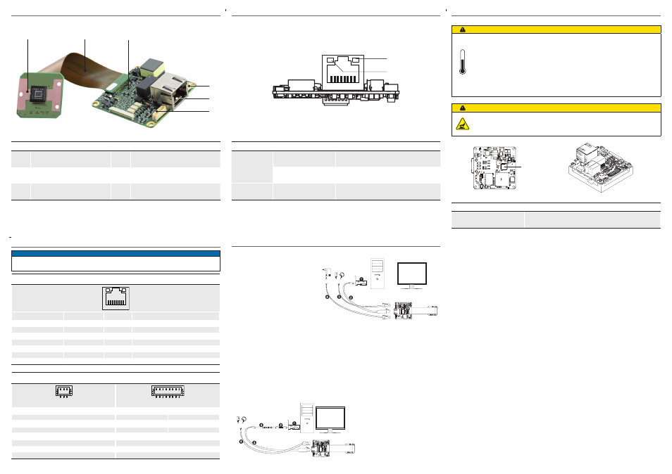
General Description
1
2
4
5
6
3
No.
Description
No.
Description
1
Sensor print
4
Power supply
2
Flexprint cable
5
Ethernet Port
3
System print
6
Digital IO
T